An edge is a line connecting two vertices that forms the side of a polygon. An edge can't be shared by more than two polygons. Also, the normals of the two polygons should be adjacent. If they aren't, you wind up with two edges that share vertices.
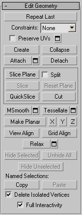
At the editable poly Edge sub-object level, you can select single and multiple edges and transform them using standard methods. This topic covers the Edit Geometry and Edit Edges rollouts; for other controls, see Editable Poly.
Example: To use the Cut and Turn features:
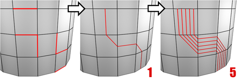
3ds Max provides a convenient function for turning edges, which, along with the Cut feature, streamlines the custom modeling process considerably. Specifically, cutting a new polygon into existing geometry minimizes the number of extra visible edges, typically adding none or one. And after using cut, the Turn function lets you adjust any diagonal with a single click.
 Create panel
 (Geometry) Standard Primitives Object Type rollout.
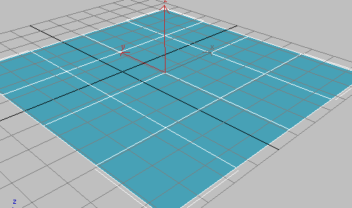
By default, the Plane object is divided into 4 x 4 polygons. If you don't see the polygons in the Perspective viewport, press F4 to activate Edged Faces view mode.
To convert the object, right-click once in the Perspective viewport to exit create mode. This leaves the object selected.
Right-click again in the Perspective viewport, and then at the bottom of the Transform quadrant, choose Convert To Convert To Editable Poly. Alternatively, apply the Edit Poly modifier.
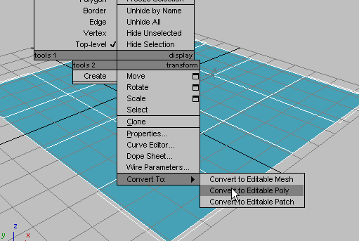
The object is now an editable poly and the command panel switches to the Modify panel.
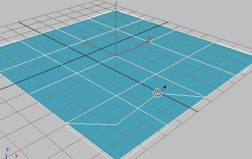
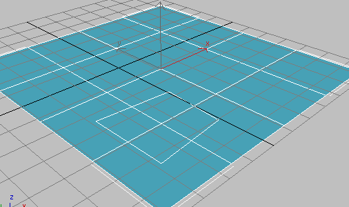
Two or three lines appear and move as you move the mouse. One line connects the mouse cursor to the original click location, and indicates where the next cut will appear when you click the mouse button. Another connects to a corner of the polygon; this connection changes depending on the mouse position. And, if the cursor isn't over an edge or a vertex (it changes appearance if it is, depending on which), a third line connects the mouse cursor to another vertex.
This demonstrates one aspect of the new Cut functionality; in previous versions, the first click in a Cut operation connected to two corners of the polygon.
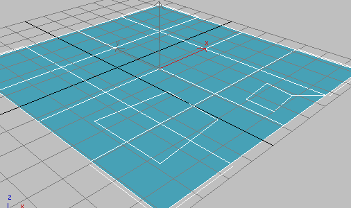
The result is a rectangle across four polygons, without any connecting visible edges. In previous versions, you would have had eight connecting visible edges: two in each of the original polygons. Note that all the edges you created are selected, and ready for further transformation or editing.
In this case you end up with a single, additional visible edge instead of seven, as in previous versions. The edge connects corner of the new polygon with a corner of the original one. This new edge is not selected, but the ones you created explicitly are.
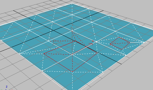
Connecting the remaining corners are a number of diagonals, which serve to fully triangulate the polygons. The new Turn function lets you manipulate each of these with a single click.
All diagonals, including those created from the Cut operations, appear as dashed lines.
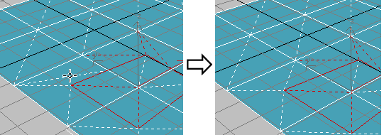
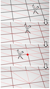
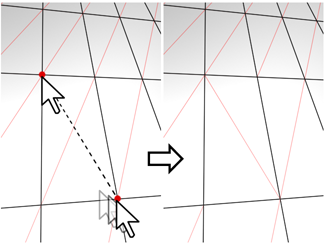
In Turn mode, click a diagonal (dashed line) once to turn it.
Each diagonal has only two different available positions, given no changes in any other diagonals' or edges' positions.
Compare this with the Edit Triangulation tool, with which you must click two vertices to change a diagonal's position.
This simple demonstration shows how, when manually subdividing a polygon mesh for modeling and animation purposes, you can save a good deal of time by using the Cut and Turn tools in 3ds Max.
To create a shape from one or more edges:
 Select the edges you want to make into shapes.
The resulting shape consists of one or more splines whose vertices are coincident with the vertices in the selected edges. The Smooth option results in vertices using smooth values, while the Linear option results in linear splines with corner vertices.
If the selected edges are not continuous, or if they branch, the resulting shape will consist of more than one spline. When the Create Shape function runs into a branching 'Y' in the edges, it makes an arbitrary decision as to which edge produces which spline. If you need to control this, select only those edges that will result in a single spline, and perform a Create Shape operation repeatedly to make the correct number of shapes. Finally, use Attach in the Editable Spline to combine the shapes into one.
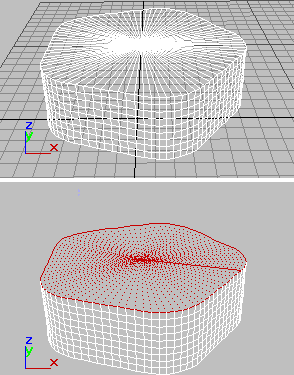
Above: Original object
Below: Object with edges selected
Above: Selected edges removed from original object
Below: Unwanted edges removed
Soft Selection controls apply a smooth falloff between selected sub-objects and unselected ones. When Use Soft Selection is on, unselected sub-objects near your selection are given partial selection values. These values are shown in the viewports by means of a color gradient on the vertices, and optionally on the faces. They affect most types of sub-object deformations, such as the Move, Rotate, and Scale functions, as well as any deformation modifiers (such as Bend) applied to the object. This provides a magnet-like effect with a sphere of influence around the selection.
For more information, see Soft Selection Rollout.
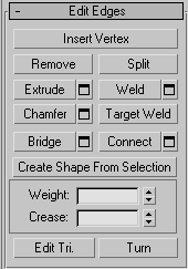
This rollout includes commands specific to edge editing.
Deletes selected edges and combines the polygons that use them.
Removing one edge is like making it invisible. The mesh is affected only when all or all but one of the edges depending on one vertex are removed. At that point, the vertex itself is deleted and the surface is retriangulated.
To delete the associated vertices when you remove edges, press and hold Ctrl while executing a Remove operation, either by mouse or with the Backspace key. This option, called Clean Remove, ensures that the remaining polygons are planar.
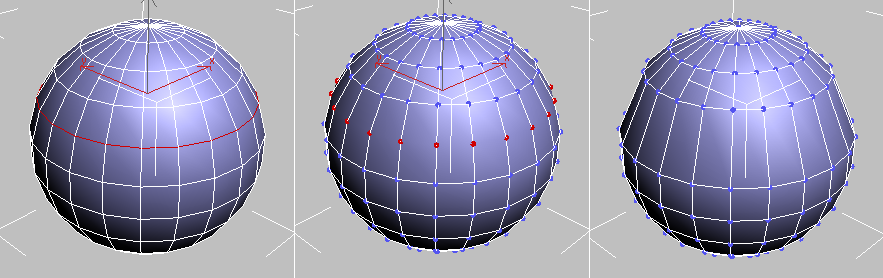
Left: The original edge selection
Center: Standard Remove operation leaves extra vertices.
Right: Clean Remove with Ctrl+Remove deletes the extra vertices.
Edges with the same polygon on both sides usually can't be removed.
Divides the mesh along the selected edges.
This does nothing when applied to a single edge in the middle of a mesh. The vertices at the end of affected edges must be separable in order for this option to work. For example, it would work on a single edge that intersects an existing border, since the border vertex can be split in two. Additionally, two adjacent edges could be split in the middle of a grid or sphere, since the shared vertex can be split.
Lets you extrude edges manually via direct manipulation in the viewport. Click this button, and then drag vertically on any edge to extrude it.
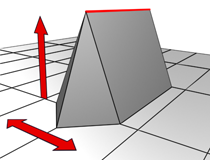
When extruding a vertex or edge interactively in the viewport, you set the extrusion height by moving the mouse vertically and the base width by moving the mouse horizontally.
Extruding an edge moves it along a normal and creates new polygons that form the sides of the extrusion, connecting the edge to the object. The extrusion has either three or four sides; three if the edge was on a border, or four if it was shared by two polygons. As you increase the length of the extrusion, the base increases in size, to the extent of the vertices adjacent to the extruded edge's endpoints.
Following are important aspects of edge extrusion:
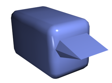
Chamfer box showing extruded edge
 Extrude Settings
Opens the Extrude Edges caddy, which lets you perform extrusion via interactive manipulation.
If you click this button after performing a manual extrusion, the same extrusion is performed on the current selection as a preview and the caddy opens with Extrusion Height set to the amount of the last manual extrusion.
Combines selected edges that fall within the threshold specified on the Weld caddy.
You can weld only edges that have one polygon attached; that is, edges on a border. Also, you cannot perform a weld operation that would result in illegal geometry (e.g., an edge shared by more than two polygons). For example, you cannot weld opposite edges on the border of a box that has a side removed.
Opens the Weld Edges caddy, which lets you specify the weld threshold.
Click this button and then drag edges in the active object. To chamfer edges numerically, click the Chamfer Settings button and change the Chamfer Amount value.
If you chamfer multiple selected edges, all of them are chamfered identically. If you drag an unselected edge, any selected edges are first deselected.
An edge chamfer "chops off" the selected edges, creating a new polygon connecting new points on all visible edges leading to the original vertex. The new edges are exactly <chamfer amount> distance from the original edge along each of these edges. New chamfer faces are created with the material ID of one of the neighboring faces (picked at random) and a smoothing group which is an intersection of all neighboring smoothing groups.
For example, if you chamfer one edge of a box, each corner vertex is replaced by two vertices moving along the visible edges that lead to the corner. Outside faces are rearranged and split to use these new vertices, and a new polygon is created at the corner.
Using Chamfer at the Edge level
Alternatively, you can create open space around the chamfered edges; for details, see Chamfer.
Chamfer SettingsOpens the Chamfer caddy, which lets you chamfer edges via interactive manipulation and toggle the Open option.
If you click this button after performing a manual chamfer, the same chamfer is performed on the current selection as a preview and the caddy opens with Chamfer Amount set to the amount of the last manual chamfer.
Allows you to select an edge and weld it to a target edge. When positioned over an edge, the cursor changes to a + cursor. Click and move the mouse and a dashed line appears from the vertex with an arrow cursor at the other end of the line. Position the cursor over another edge and when the + cursor appears again, click the mouse. The first edge is moved to the position of the second, and the two are welded.
You can weld only edges that have one polygon attached; that is, edges on a border. Also, you cannot perform a weld operation that would result in illegal geometry (e.g., an edge shared by more than two polygons). For example, you cannot weld opposite edges on the border of a box that has a side removed.
Connects border edges on an object with a polygon “bridge.” Bridge connects only border edges; that is, edges that have a polygon on only one side. This tool is particularly useful when creating edge loops or profiles.
There are two ways to use Bridge in Direct Manipulation mode (that is, without opening the Bridge Edges caddy):
The new polygons that result from a Bridge operation are automatically selected; you can see this by accessing the Polygon sub-object level.
Using Bridge at the Edge level
Bridge SettingsOpens the Bridge Edges caddy, which lets you add polygons between pairs of edges via interactive manipulation.
Creates new edges between pairs of selected edges using the current Connect Edges settings. Connect is particularly useful for creating or refining edge loops.
Connecting two or more edges using the Settings dialog creates equally spaced edges. The number of edges is set in the dialog. When you click the Connect button, the current dialog settings are applied to the selection.
Connect SettingsOpens the Connect Edges caddy, which lets you preview the Connect results, specify the number of edge segments created by the operation, and set spacing and placement for the new edges.
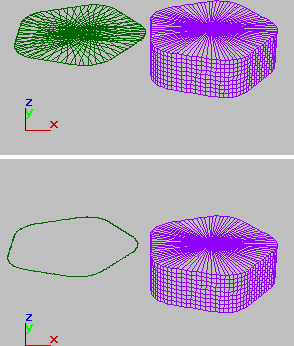
After selecting one or more edges, click this button to create a spline shape from the selected edges. A Create Shape dialog appears, letting you name the shape and set it to Smooth or Linear. The new shape's pivot is placed at the center of the poly object.
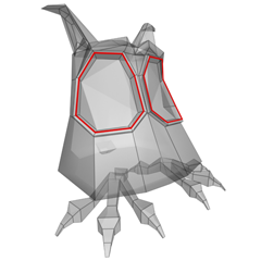
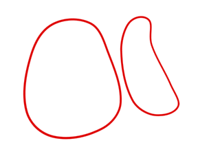
An edge selection (top); a smooth shape (center); a linear shape (bottom)
Sets the weight of selected edges. Used by the NURMS subdivision option and by the MeshSmooth modifier.
Increasing an edge weight tends to push the smoothed result away.
 .
.
For instructions for using the caddy, see The Caddy Interface.
Specifies how much creasing is performed on the selected edge or edges. Used by the NURMS subdivision option and by the MeshSmooth modifier.
At low settings, the edge is relatively smooth. At higher settings, the crease becomes increasingly visible. At 1.0, the highest setting, the edge becomes a hard crease.
 .
.
For instructions for using the caddy, see The Caddy Interface.
Lets you modify how polygons are subdivided into triangles by drawing internal edges, or diagonals.
In Edit Triangulation mode, you can see the current triangulation in the viewport, and change it by clicking two vertices on the same polygon.
To edit triangulation manually, turn on this button. The hidden edges appear. Click a polygon vertex. A rubber-band line appears, attached to the cursor. Click a non-adjacent vertex to create a new triangulation for the polygon.
Lets you modify how polygons are subdivided into triangles by clicking diagonals. When you activate Turn, the diagonals become visible as dashed lines in wireframe and edged-faces views. In Turn mode, click a diagonal to change its position. To exit Turn mode, right-click in the viewport or click the Turn button again.
Each diagonal has only two available positions at any given time, so clicking a diagonal twice in succession simply returns it to its original position. But changing the position of a nearby diagonal can make a different alternate position available to a diagonal.
For more information on how to use Turn with the enhanced Cut tool, see this procedure.
For information about the Subdivision Surface rollout settings, see Subdivision Surface Rollout (Polymesh).
Subdivision Displacement rollout
For information about the Subdivision Displacement rollout settings, see Subdivision Displacement Rollout (Polymesh).
Paint Deformation lets you stroke elevated and indented areas directly onto object surfaces. For more information, see Paint Deformation Rollout (Polymesh).


 Modify panel