A border is a linear section of a mesh that can generally be described as the edge of a hole. This is usually a sequence of edges with polygons on only one side. For example, a box primitive doesn't have a border, but the teapot object has several: on the lid, on the body, on the spout, and two on the handle. If you create a cylinder and then delete an end polygon, the adjacent row of edges forms a border.
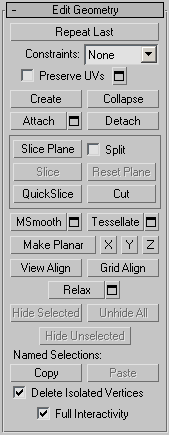
At the editable poly Border sub-object level, you can select single and multiple borders and transform them using standard methods. This topic covers the Edit Geometry and Edit Borders rollouts; for other controls, see Editable Poly.
Soft Selection controls apply a smooth falloff between selected sub-objects and unselected ones. When Use Soft Selection is on, unselected sub-objects near your selection are given partial selection values. These values are shown in the viewports by means of a color gradient on the vertices, and optionally on the faces. They affect most types of sub-object deformations, such as the Move, Rotate, and Scale functions, as well as any deformation modifiers (such as Bend) applied to the object. This provides a magnet-like effect with a sphere of influence around the selection.
For more information, see Soft Selection Rollout.
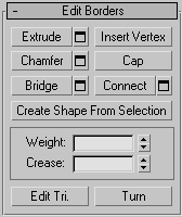
This rollout includes commands specific to editing borders.
Lets you extrude a border manually via direct manipulation in the viewport. Click this button, and then drag vertically on any border to extrude it.
Extruding a border moves it along a normal and creates new polygons that form the sides of the extrusion, connecting the border to the object. The extrusion can form a varying number of additional sides, depending on the geometry near the border. As you increase the length of the extrusion, the base increases in size, to the extent of the vertices adjacent to the extruded border's endpoints.
Following are important aspects of border extrusion:
 Extrude Settings
Opens the Extrude Edges caddy, which lets you perform extrusion via interactive manipulation.
If you click this button after performing a manual extrusion, the same extrusion is performed on the current selection as a preview and the caddy opens with Extrusion Height set to the amount of the last manual extrusion.
Lets you subdivide border edges manually.
After turning on Insert Vertex, click a border edge to add a vertex at that location. You can continue subdividing border edges as long as the command is active.
To stop inserting vertices, right-click in the viewport, or click Insert Vertex again to turn it off.
Click this button and then drag a border in the active object. The border need not be selected first.
If you chamfer multiple selected borders, all of them are chamfered identically. If you drag an unselected border, any selected borders are first deselected.
A border chamfer essentially “frames” the border edges, creating a new set of edges paralleling the border edges, plus new diagonal edges at any corners. These new edges are exactly <chamfer amount> distance from the original edges. New chamfer faces are created with the material ID of one of the neighboring faces (picked at random) and a smoothing group which is an intersection of all neighboring smoothing groups.
Alternatively, you can create open space around the chamfered borders, essentially cutting away at the open edges; for details, see Chamfer.
Chamfer SettingsOpens the Chamfer Edges caddy, which lets you chamfer borders via interactive manipulation and toggle the Open option.
If you click this button after performing a manual chamfer, the same chamfer is performed on the current selection as a preview and the dialog opens with Chamfer Amount set to the amount of the last manual chamfer.
Connects pairs of borders on an object with polygon “bridges.” There are two ways to use Bridge in Direct Manipulation mode (that is, without opening the Bridge Settings dialog):
The new polygons that result from a Bridge operation are automatically selected; you can see this by accessing the Polygon sub-object level.
Using Bridge at the Border level.
Bridge SettingsOpens the Bridge caddy, which lets you connect pairs of borders via interactive manipulation.
Creates new edges between pairs of selected border edges. The edges are connected from their midpoints.
You can connect only edges on the same polygon.
Connect will not let the new edges cross. Thus, for example, if you select all four edges of a four-sided polygon and then click Connect, only neighboring edges are connected, resulting in a diamond pattern.
Connect SettingsSets the weight of selected borders. Used by the NURMS subdivision option.
Increasing an edge weight tends to push the smoothed result away.
Specifies how much creasing is performed on the selected border or borders. Used by the NURMS subdivision option.
At low settings, the border is relatively smooth. At higher settings, the crease becomes increasingly visible. At 1.0, the highest setting, the border is not smoothed at all.
Lets you modify how polygons are subdivided into triangles by drawing internal edges, or diagonals.
To edit triangulation manually, turn on this button. The hidden edges appear. Click a polygon vertex. A rubber-band line appears, attached to the cursor. Click a non-adjacent vertex to create a new triangulation for the polygon.
Lets you modify how polygons are subdivided into triangles by clicking diagonals. When you activate Turn, the diagonals become visible as dashed lines in wireframe and edged-faces views. In Turn mode, click a diagonal to change its position. To exit Turn mode, right-click in the viewport or click the Turn button again.
Each diagonal has only two available positions at any given time, so clicking a diagonal twice in succession simply returns it to its original position. But changing the position of a nearby diagonal can make a different alternate position available to a diagonal.
For more information on how to use Turn with the enhanced Cut tool, see this procedure.
For information about the Subdivision Surface rollout settings, see Subdivision Surface Rollout (Polymesh).
Subdivision Displacement rollout
For information about the Subdivision Displacement rollout settings, see Subdivision Displacement Rollout (Polymesh).
Paint Deformation lets you stroke elevated and indented areas directly onto object surfaces. For more information, see Paint Deformation Rollout (Polymesh).


 Modify panel
  select any open edge.