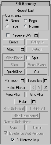
The Edit Geometry rollout provides global controls for changing the geometry of the poly object, at either the top (Object) level or the sub-object levels. The controls are the same at all levels, except as noted in the descriptions below.
Repeats the most recently used command.
For example, if you extrude a polygon, and want to apply the same extrusion to several others, select the others, and then click Repeat Last.
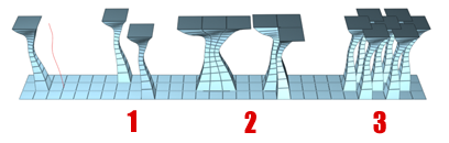
You can apply a spline extrusion of a single polygon (left) repeatedly to other single polygons (1) or to multiple polygon selections, contiguous (2) or not (3).
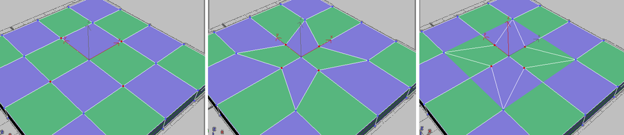
Lets you use existing geometry to constrain sub-object transformation. Choose the constraint type:
When set to Edge, moving a vertex will slide it along one of the existing edges, depending on the direction of the transformation. If set to Face, the vertex moves only on the polygon’s surface.
When on, you can edit sub-objects without affecting the object's UV mapping. You can choose any of an object's mapping channels to preserve or not; see Preserve UVs Settings, following. Default=off.
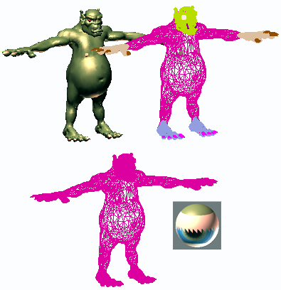
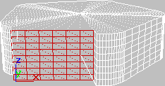
Without Preserve UVs, there is always a direct correspondence between an object's geometry and its UV mapping. For example, if you map an object and then move vertices, the texture moves along with the sub-objects, whether you want it to or not. If you turn on Preserve UVs, you can perform minor editing tasks without changing the mapping.
Original object with texture map (left); Scaled vertices with Preserve UVs off (center); Scaled vertices with Preserve UVs on (right)
 Preserve UVs Settings
Opens the Preserve Map Channels dialog, which lets you specify which vertex color channels and/or texture channels (map channels) to preserve. By default, all vertex color channels are off (not preserved), and all texture channels are on (preserved).
Lets you create new geometry. How this button behaves depends on which level is active:
While creating a polygon at the Polygon or Element level, you can delete the most recently added vertex by pressing Backspace. You can do this repeatedly to remove added vertices in reverse order of placement.
You can start creating polygons in any viewport, but all subsequent clicks must take place in the same viewport.
Edges you create separate the polygons. For example, by creating an edge inside a quadrilateral polygon, you turn it into two triangles.
Lets you attach other objects in the scene to the selected poly object. After activating Attach, click an object to attach to the selected object. Attach remains active, so you can continue clicking objects to attach them. To exit, right-click in the active viewport or click the Attach button again.
You can attach any type of object, including splines, patch objects, and NURBS surfaces. Attaching a non-mesh object converts it to editable-poly format.
When you attach an object, the materials of the two objects are combined in the following way:
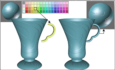
Handle inherits material from the cup it is being attached to.
Attach remains active in all sub-object levels, but always applies to objects.
Attach ListLets you attach other objects in the scene to the selected mesh. Click to open the Attach List dialog, which works like Select From Scene to let you choose multiple objects to attach.
Separates the selected sub–objects and associated polygons as a new object or element(s).
With an Editable Poly object, when you click Detach, the software prompts you for the options specified on the Detach dialog. With an Edit Poly object, Detach on the Modify panel automatically uses those settings. To change them, click Detach Settings (see following).
Detach SettingsOpens the Detach dialog, which lets you set several options. Available only with Edit Poly objects; with Editable Poly, this dialog opens automatically when you click Detach.
These knife-like tools let you subdivide the poly mesh along a plane (Slice) or in a specific area (Cut). Also see Full Interactivity.
Creates a gizmo for a slice plane that you can position and rotate to specify where to slice. Also enables the Slice and Reset Plane buttons; click Slice to create new edges where the plane intersects the geometry.
If you use Slice Plane from the modeling ribbon, the Slice, Split, and Reset Plane controls are available on the Slice Mode contextual panel.
If snapping is off, you see a preview of the slice as you transform the slice plane. To perform the slice, click the Slice button.
Performs the slice operation at the location of the slice plane. Available only when Slice Plane is on. This tool slices the poly just like the “Operate On: Polygons” mode of the Slice modifier.
Left: Using Slice; Right: After slicing and moving the pieces apart
Lets you quickly slice the object without having to manipulate a gizmo. Make a selection, click QuickSlice, and then click once at the slice start point and again at its endpoint. You can continue slicing the selection while the command is active.
To stop slicing, right-click in the viewport, or click QuickSlice again to turn it off.
With Quickslice on, you can draw a line across your mesh in any viewport, including Perspective and Camera views. The mesh is sliced interactively as you move the line endpoint.
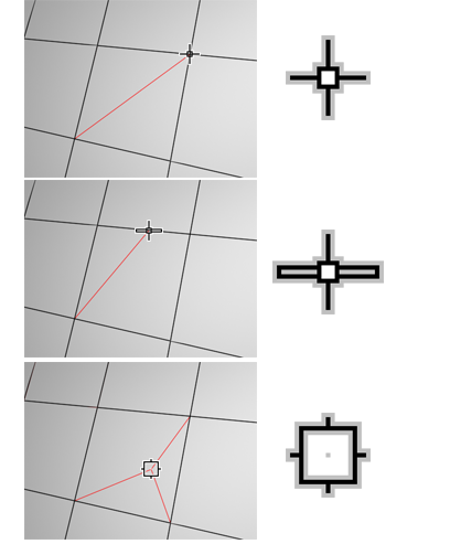
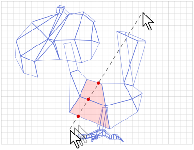
Lets you create edges from one polygon to another or within polygons. Click at the start point, move the mouse and click again, and continue moving and clicking to create new connected edges. Right-click once to exit the current cut, whereupon you can start a new one, or right-click again to exit Cut mode.
While cutting, the mouse cursor icon changes to show the type of sub-object it’s over, to which the cut will be made when you click. The following illustration shows the three different cursor icons.
Smoothes the object using the current settings. This command uses subdivision functionality similar to that of the MeshSmooth modifier with NURMS Subdivision, but unlike NURMS subdivision, it applies the smoothing instantly to the selected area of the control mesh.
Smoothing a low-poly object with NURMS subdivision
MSmooth SettingsOpens the MeshSmooth caddy, which lets you specify how smoothing is applied.
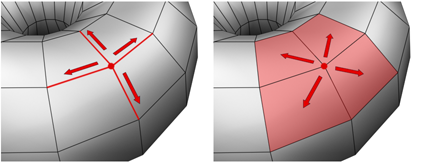
Subdivides all polygons in the object based on the Tessellation settings.
Tessellation is useful for increasing local mesh density while modeling. You can subdivide any selection of polygons. Two tessellation methods are available: Edge and Face.
Tessellate SettingsOpens the Tessellate caddy, which lets you specify how smoothing is applied.
Makes all selected sub-objects planar and aligns the plane with the corresponding plane in the object's local coordinate system. The plane used is the one to which the button axis is perpendicular; so, for example, clicking the X button aligns the object with the local YZ axis.
At the Object level, makes all vertices in the object planar.
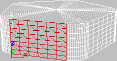
Aligns all vertices in the object to the plane of the active viewport. At sub-object levels, this function affects only selected vertices or those belonging to selected sub-objects.
In orthographic viewports, aligning to the view has the same effect as aligning to the construction grid when the home grid is active. Aligning to a perspective viewport (including camera and light views), reorients the vertices to a plane that is parallel to the camera's viewing plane. This plane is perpendicular to the view direction that is closest to the vertices' average position.
Aligns all vertices in the selected object to the plane of the current view. At sub-object levels, aligns only selected sub-objects.
This command aligns the selected vertices to the current construction plane. The current plane is specified by the active viewport in the case of the home grid. When using a grid object, the current plane is the active grid object.
Applies the Relax function to the current selection, using the current Relax settings (see following). Relax normalizes mesh spacing by moving each vertex toward the average location of its neighbors. It works the same way as the Relax modifier.
At the object level, Relax applies to the entire object. At sub-object levels, Relax applies only to the current selection.
Relax SettingsOpens the Relax caddy, which lets you specify how the Relax function is applied.
Named Selections (sub-object levels only)
Lets you copy and paste named selection sets of sub-objects between objects. Start by creating one or more named selection sets, copy one, select a different object, go to the same sub-object level, and then paste the set.
For more information, see Named Selection Sets.
Toggles the level of feedback for the QuickSlice and Cut tools, as well as all settings dialogs and caddies. Available with editable poly objects, but not the Edit Poly modifier.
When on (the default), 3ds Max updates the viewport in real time as you use the mouse to manipulate the tool or change a numeric setting. With Cut and QuickSlice, when Full Interactivity is off, only the rubber-band line is visible until you click. Similarly, with numeric settings in caddies, the final result is visible only when you release the mouse button after changing the setting.
The state of Full Interactivity doesn't affect changing a numeric setting from the keyboard. Whether it's on or off, the setting takes effect only when you exit the field by pressing Tab or Enter, or by clicking a different control in the dialog.


 Modify panel