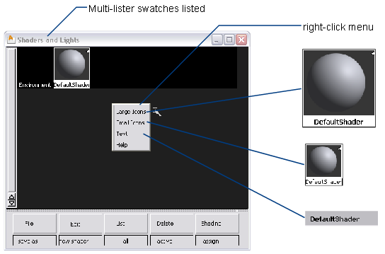
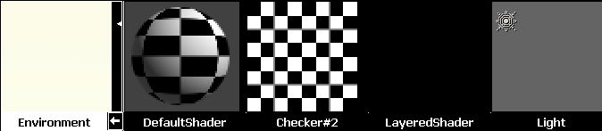
The title bar indicates the type of swatches that are listed in the Multi-lister. It also lets you control the display of swatches in the Multi-lister (text, small swatches, large swatches), and lets you close, track, and minimize/maximize the Multi-lister window.
There are five different types of swatches used in the Multi-lister: environment, shader, texture, layered shader, and light.
These five types of swatches are used to represent:
Swatches are listed in the following order: the environment, shaders, lights. Shaders and lights are listed alphabetically by name. Textures are listed next to the environment, shader, or light that they are mapped to.
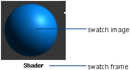
All swatches consist of an image and a frame. The image represents the appearance of the environment, shader, texture, or light. The frame contains the swatch name and any icons.
The type of swatch image and the way that you use the swatch are different for different swatch types. All swatches, however, share the following features.
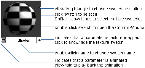
You can select a swatch by clicking on it. You can select several swatches by  -clicking on them. By double-clicking a swatch, you open its Control Window. You can then edit any parameter for that particular environment, shader, texture, or light. Use the control window
You can edit the swatch name by double-clicking on the name and typing a new name. You can change the resolution of the swatch’s image by click-dragging the white triangle on the right side of the swatch either up (higher resolution) or down (lower resolution).
If an environment, shader, texture, or light has a texture mapped to one of its parameters, the swatch will have an arrow in its bottom right corner. By clicking on this arrow, you can toggle the display of the texture in the Multi-lister.
If you have animated a parameter of an environment, shader, texture, or light, the swatch will have a diamond in its bottom left corner. By click-holding on this diamond, you can play back the animation of the swatch.
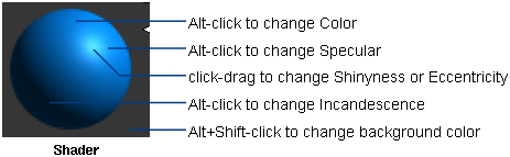
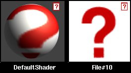
A shader swatch uses a sphere to represent the appearance of a surface. By  -clicking (Windows) or
  -clicking (Mac) on different parts of the sphere, you can open the Color Editor and edit the shader’s Color, Specular, or Incandescence settings. (By +-clicking (Windows) or +-clicking (Mac) on the background, you can open the Color Editor and edit the shader icon background color.) By click-dragging on the sphere’s highlight, you can interactively edit the shader’s
Shinyness or Eccentricity value.
-clicking (Mac) on different parts of the sphere, you can open the Color Editor and edit the shader’s Color, Specular, or Incandescence settings. (By +-clicking (Windows) or +-clicking (Mac) on the background, you can open the Color Editor and edit the shader icon background color.) By click-dragging on the sphere’s highlight, you can interactively edit the shader’s
Shinyness or Eccentricity value.
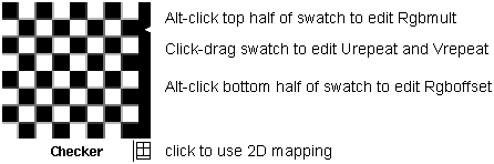
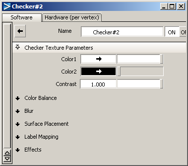
A surface texture swatch displays the two-dimensional texture. By -clicking (Windows) or -clicking (Mac) on the top half of the swatch, you can open the Color Editor and edit the texture’s Rgbmult setting. By -clicking (Windows) or -clicking (Mac) on the bottom half of the swatch, you can open the Color Editor and edit the texture’s Rgboffset setting. By click-dragging anywhere in the swatch, you can interactively edit the texture’s Urepeat and Vrepeat values.
A surface texture swatch has two texture mapping symbols in its bottom right corner. By clicking on one of these symbols you activate either 2D mapping or 3D mapping.
See Use 3D mapping to position a texture on a surface.
The Stencil texture appears black in the Multi-lister until you specify its Image.
The File texture appears black with a small question mark (?) icon until you specify its Image. If the Multi-lister cannot find a File texture’s image file, the File texture appears with both large and small question mark icons.
A layered shader represents the combination of shaders that have been layered onto a surface. The appearance of these layers is rendered onto a sphere swatch in the multilister. Click the swatch to open the layered shader editor.
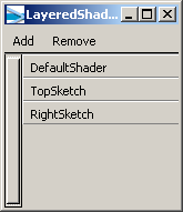
A new, empty layered shader appears black, because the layers are empty. To add shaders to a layered shader, select one or
more shaders from the Multilister window, then click Add. You can select multiple shaders by pressing the key while you select shaders.
To remove shaders from a layered shader, select one or more of the listed shaders in the Layered Shader editor, then click
Remove. You can select multiple shaders by pressing the key while you select shaders.
Use the  in the Layered Shader editor to rearrange the layers.
The window shows the layers of shaders that have been applied to a simple sphere. You can now assign this layered shader to other objects.
Environment texture and solid texture swatches
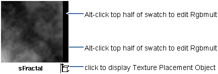
An environment or solid texture swatch uses a two-dimensional pattern to represent the three-dimensional texture. By -clicking (Windows) or -clicking (Mac) on the top half of the swatch, you can open the Color Editor and edit the texture’s Rgbmult setting. By -clicking (Windows) or -clicking (Mac) on the bottom half of the swatch, you can open the Color Editor and edit the texture’s Rgboffset setting.
See Apply 3D environments and Apply solid textures.
An environment or solid texture has a texture placement symbol in its bottom right corner. By clicking on this symbol you can display the texture’s Texture Placement Object in the modeling windows.
The Ball, Cube, Sphere, Projection, and Volume textures appear black in the Multi-lister until you specify an image file or series of image files for them. The sCloud texture always appears black in the Multi-lister; the shader it is mapped to displays the actual texture.
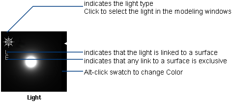
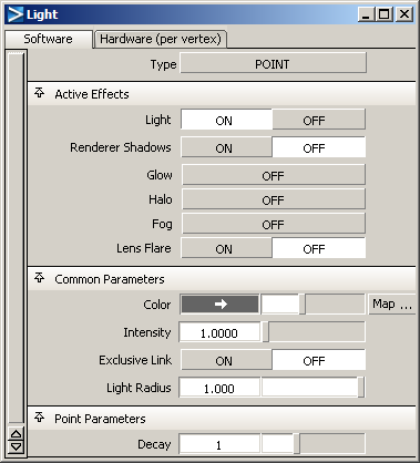
A light swatch represents a light as viewed from 10 units away with a 20 degree field of view. By -clicking (Windows) or -clicking (Mac) the swatch you can open the Color Editor and edit the light’s Color parameter.
A light swatch has a light type symbol in its top left corner. If the light has a force component, the light swatch will also have a force type symbol. If the light is linked to a surface, the light swatch will also have an L symbol. If a light’s link to a surface is exclusive, the light swatch will also have an E symbol.
See Create a light.
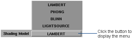
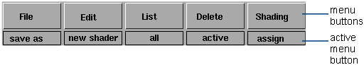
The Multi-lister menus contain tools to create, edit, manage, and display shaders, textures, lights, and the environment. To display a menu, click and hold the mouse on a menu button at the bottom of the Multi-Lister window. The default active menu item is displayed below each button.
The File menu contains tools to save and retrieve lights, environments, shaders, and textures.
Opens the File Requestor and lets you retrieve any shader that was previously saved using File > Save in the Multi-lister. The default directory is the directory that you last used to save.
Opens the File Requestor and lets you retrieve any texture that was previously saved using File > Save in the Multi-lister, into the active Multi-lister swatch (environment, shader, texture, or light).
The retrieved texture is automatically assigned to the Color parameter (if the active Multi-lister swatch is an environment, shader, or light) or to the Rgbmult parameter (if the active Multi-lister swatch is a texture). Only one Multi-lister swatch can be active when using Texture Browse.
Opens the File Requestor and lets you retrieve any light (including glows) that was previously saved using File > Save in the Multi-lister. The default directory is the directory that you last used to save.
Opens the File Requestor and lets you retrieve any environment that was previously saved using File > Save in the Multi-lister. If you retrieve an environment, it will automatically replace your current environment. The default directory is the directory
that you last used to save.
Enables you to retrieve a previously-saved layered shader. Retrieving a layered shader also retrieves all shaders referenced by the layered shader.
Saves the active environment, shader, texture or light in the Multi-lister to a file that is independent from your scene’s wire file. The file’s name can either be the current environment/shader/texture/light name (Save) or a name that you specify when saving (Save as). You can retrieve files saved using Save as/Save into other wire files using Shader Browse, Texture Browse, Light Browse, and Environment Browse.
Note the following when using Save as or Save:
or File > Save As). However, you cannot easily access this information from other wire files.
The Edit menu contains tools for creating and editing environments, shaders, textures, and lights.
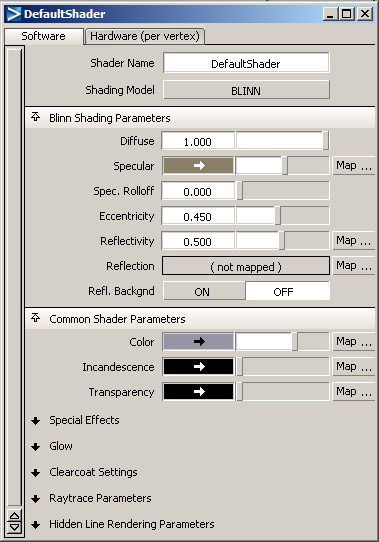
Creates a new shader that is identical to the default shader. To create a new shader based on a shader other than the default
shader, use Edit > Copy . To change the default shader for all future sessions, save a shader in the default shader directory with the name DefaultShader. If you edit the default shader in the Multi-lister, but don’t save it, the changes will only last for that session.
Creates a new point light (based on the last point light you created) located at (0,0,0). To set options for the new light,
change the values in the Point Light Options box and save them before selecting New Light. To create a new light based on an existing light, use Edit > Copy.
Creates a new, empty layered shader. Double-click the swatch to open the LayeredShader editor.
Creates a copy of the currently active shader or light. Note the following when using Copy:
Copies selected parameter settings from one environment/shader/texture/light to another. Note the following when using Copy Parameters:
Creates a new shader for selected surfaces, where all solid textures are replaced by a file surface texture so that the appearance of the objects does not change. These surface textures recreate the shading qualities of the solid texture. In effect, this freezes the solid texture onto the surface.
Note the following when using Convert Solid Tex:
 during the Convert Solid Tex operation, the files created up to that point will be correct, but will not necessarily be assigned. Even if you delete the
shader created by Convert Solid Tex, the image files still exist in a directory with the same name as the original shader in the current pix directory. If you
perform a second Convert Solid Tex operation using the same shader and objects, the previously created files are overwritten without warning.
to paste).
during the Convert Solid Tex operation, the files created up to that point will be correct, but will not necessarily be assigned. Even if you delete the
shader created by Convert Solid Tex, the image files still exist in a directory with the same name as the original shader in the current pix directory. If you
perform a second Convert Solid Tex operation using the same shader and objects, the previously created files are overwritten without warning.
to paste).
Use Convert Solid Tex in the following situations:
Enables you to retrieve information from an active surface, andview the shaders applied to that selected surface in the layered shader editor.
Opens the Control Window for the active environment, shader, texture, or light. You can also open the Control Window by double-clicking the environment/shader/texture/light swatch in the Multi-lister.
Opens the Color Editor for the Color parameter of the active environment, shader, or light or for the Rgbmult parameter of the active texture. You can also open the Color Editor by clicking the color field of a parameter in the Control Window.
See Change colors.
Opens the Texture Procedures window for the Color parameter of the active environment, shader, or light or for the Rgbmult parameter of the active texture. You can also open the Texture Procedures window by clicking the Map button beside a texturable parameter in the Control Window.
Cancels all changes made to the active environment, shader, texture, or light since it became active. This includes all changes made to any textures assigned to it.
The menu item you use to open the Multi-lister determines the type of swatches initially displayed in the Multi-lister (see Open the Multi-lister). The List menu lets you change the type of swatches that are displayed in the Multi-lister. The Multi-lister title bar indicates the type of swatches currently displayed in the Multi-lister.
Displays the environment and all shaders, layered shaders, textures, lights, and glows currently in memory.
Displays the environment and all shaders currently in memory, including textures that are assigned to the environment or to any shader.
Displays all lights in your scene that have a Light component, including textures that are assigned to any of these lights.
Displays all lights in your scene that have a Glow, Halo, Fog, or Lens Flare component and all shaders currently in memory that have a Glow component, including textures that are assigned to any of these lights or shaders.
Displays all lights in your scene that are picked (active) and all shaders currently in memory that are assigned to active objects, including textures that are assigned to any of these lights or shaders. Selecting List > Picked displays lights with or without a Light component.
Displays all lights in your scene that are linked to surfaces, including textures that are assigned to any of these lights. Selecting List > Linked Lights displays lights with or without a Light component.
See Link a light.
Displays all lights in your scene that have a Light component and are not exclusively linked to surfaces, including textures that are assigned to any of these lights.
See Exclusive Link.
Removes from display all items that are not layered shaders.
The Delete menu contains tools to delete shaders, textures, and lights from the Multi-lister. You cannot delete the environment or the default shader. If you try to delete either of them, they will reset to their default parameters.
Deletes all selected shaders, textures, and lights, including textures that are assigned to them. To select multiple shaders,
textures, and lights, click one shader/texture/light, then hold the key and click any other shaders/textures/lights.
Deletes all shaders, textures, and lights.
Deletes all lights, including textures that are assigned to lights. Selecting Delete > Lights deletes lights with or without a Light component.
Deletes all shaders, including textures that are assigned to shaders.
Deletes all shaders not currently assigned to objects in your scene, including textures that are assigned to any of these shaders.
Deletes all layered shaders from the multilister.
The Shading menu contains tools to assign and layer shaders to objects, link and unlink lights, and pick and list objects.
Assigns the active shader to all active objects (surfaces or meshes) in your scene.
If a shader is already assigned to an active object when you select Assign Shader, the active shader replaces it. If you assign a shader to the wrong object or overwrite an existing shader assignment, you must re-assign the original shader to the object.
Layers the active shader onto all active objects in your scene, on top of any shaders previously assigned or layered. The Transparency setting of a shader layered on top of another shader determines the visibility of shaders beneath it.
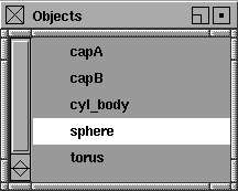
Displays a window that lists all objects to which the active shader is assigned or all objects to which the active light is linked.
The Objects window lists lights with or without a Light component. If you select a different shader or light while the Objects window is still open, the list is updated. Active objects appear highlighted in the Objects window.
Selects all objects to which the active shader is assigned or all objects to which the active light is linked (including the light itself).
Although you can select Shading > Pick Objects with multiple shaders or lights selected, only the first shader or light that you select is used to pick objects.
Links active surfaces to the active light. See Link a light. Selecting Shading > Link Lights links lights with or without a Light component.
Removes the link between the active light and the active surfaces. Selecting Shading > Unlink Lights unlinks lights with or without a Light component.
The Control Window is sometimes referred to as the Environment Editor, Shader Editor, Texture Editor, or Light Editor.
The Control Window is the interface that you use to edit shaders, textures, lights, and the environment. You can also use the Control Window to access the Color Editor.
The Control Window contains a list of parameters for the selected swatch in the Multi-lister, and allows you to edit these parameter values or settings interactively. There are four different types of Control Window: environment, texture, shader, and light.
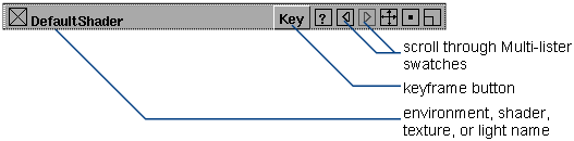
The title bar indicates the name of the active environment, shader, texture, or light in the Multi-lister. It also contains buttons or icons that let you set a keyframe for a parameter, or scroll through the Multi-lister swatches.
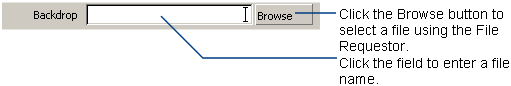
Parameters control the appearance of shaders, textures, lights, and the environment. Each parameter has a name, which describes the parameter, and a field, which specifies (and allows you to change) the parameter’s setting or value. The Control Window contains several different types of fields: name fields, file name fields, toggle fields, menu fields, numeric fields, and color fields.
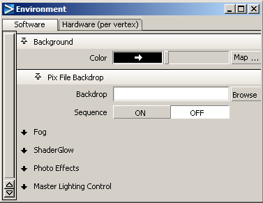
All the parameters are displayed on the Software tab; a selection of applicable parameters is displayed on the Hardware tab.
The hardware tab is labelled either Per Pixel or Per Vertex, depending on the Shading Method selected for WindowDisplay > Hardware Shade .
.
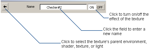
Name fields let you change the name of a shader or texture by clicking in the field and typing a new name. Textures also have an arrow button on the left side of the name field, and ON and OFF buttons on the right side of the name field. The arrow button lets you select the texture’s parent swatch in the Multi-lister (that is, the environment, shader, texture, or light that the texture is mapped to). The ON and OFF buttons let you turn the effect of the texture on or off.
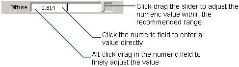
Numeric fields let you enter a number using either the keyboard or a slider beside the field. (You can also hold down the
(Windows) or (Mac) key and drag the mouse in the numeric field to make fine adjustments to the value.) Each numeric field has a valid
range (the range of values you can enter by typing in the field) and a slider range (the range of values you can enter using
the slider). The slider range represents the recommended range of values for that parameter. The valid range is negative infinity
to positive infinity for all numeric fields unless otherwise stated.
Some numeric fields also have a Map button (for example, Reflectivity).
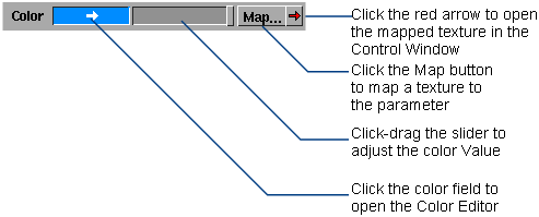
Color fields let you specify the color value by using the slider, specify the color by clicking the color field and opening the Color Editor, or map a texture to the parameter by clicking the Map button. If you map a texture to a color field, a red arrow button appears to the right of the Map button. By clicking this red arrow you can open the Control Window for that texture.
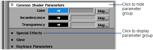
In the Control Window, parameters are organized in groups. You can display or hide a parameter group by clicking on the group name.
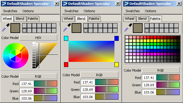
The Color Editor is the interface that you use to change the colors of environments, shaders, textures, and lights by that have a color field in the Control Window.
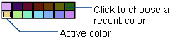
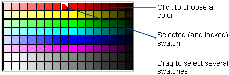
The color editor has three tabs that enable you to choose color based on your preferred method: a color wheel and triangle; a box for blending between four colors, and a palette of colors.
Resets the Swatchesto their default setting (except for locked swatches).
When several swatches in the Swatches area are selected, Ramp Selected creates a ramp of swatches gradually blending between the color of the first selected swatch and the color of the last selected swatch.

Locks the selected swatches in the Swatches area so you cannot delete them (by choosing Swatches > Delete Selected or Swatches > Reset to Default). A locked swatch has anwhite triangle in the upper right corner.

Unlocks the selected swatches in the Swatches area so you can delete them (by choosing Swatches > Delete Selected or Swatches > Reset to Default).
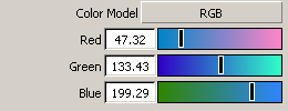
Controls whether the sliders use the HSL, HSV, RGB, or CMY color model.
See Color Models.
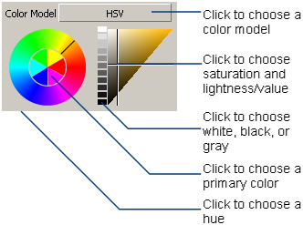
This area lets you choose a color using a color wheel and triangle.
Controls whether the color triangle uses the HSL or HSV color model.
Lets you choose:
white, black, or gray by clicking on the column of swatches
a saturation and lightness/value by clicking in the triangle.
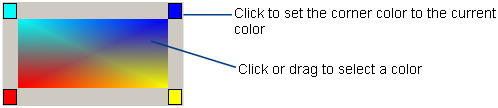
The blending box represents a blend of four colors (the colors in the four corner squares of the palette). You can use the blending box to select a color by clicking or dragging anywhere within the box.
You can change the corner colors of the box by setting the current color (for example, using the sliders), and then clicking a corner square of the blending box.
The Color Editor Picker and Sliders can represent color using various color models:
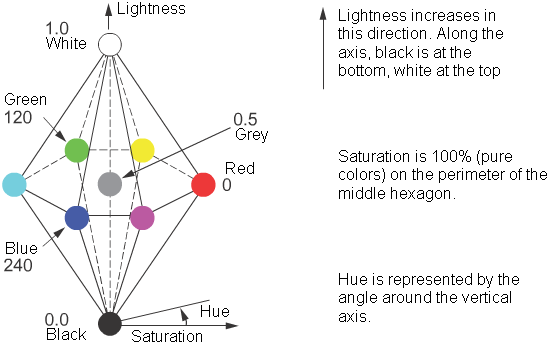
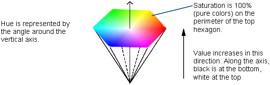
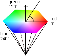
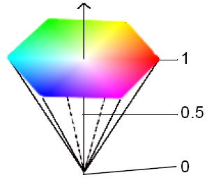
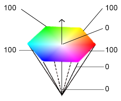
The HSL color model uses dimensions that are familiar to artists to specify colors: hue, lightness, and saturation. These three dimensions are represented by a double-hexcone.
There is one main difference between the HSL and HSV color models. In the HSV color model, both fully saturated colors (for example, pure red) and white have a value of 100%. In the HSL color model, fully saturated colors have a lightness (value) of 50% and white has a lightness (value) of 100%. In the HSL color model, pure white is perceived to be “lighter” than fully saturated colors (for example, pure red).
Hue is the quality humans use to distinguish one color from another. For example, red, green, and yellow are hues. In the HSL double-hexcone, hue is measured by the angle around the vertical axis. Red is at 0°, green at 120°, and blue at 240°.
Saturation is the quality that distinguishes a strong color from a weak one. At 100% saturation, the hue is perceived at its strongest; 0% saturation is grayscale — there is no hue, only black, white, or a shade of gray. In the HSL double-hexcone, 100% saturation is at the perimeter of the hexagon, and 0% saturation is at the central axis of the double-hexcone.
Lightness distinguishes light colors from dark ones. Black has a lightness of 0, and white has a lightness of 1 (and a saturation of 0). The bottom point of the double-hexcone has 0 lightness; this increases along the axis of the double-cone to 1 at the top point.
Saturation is the quality that distinguishes a strong color from a weak one. At 100% saturation, the hue is perceived at its strongest; 0% saturation is grayscale — there is no hue, only black, white, or a shade of gray. In the HSV hexcone, 100% saturation is at the perimeter of the hexagon, and 0% saturation is at the central axis of the hexcone.
Red, green, and blue are the additive primary colors. The RGB color model describes how red, green, or blue light combines at different intensities to produce different colors. In Alias, each component color can have a value from 0 (zero intensity) to 1, 100, or 255 (full intensity).
At full intensity red, green, and blue light combine to form white light. This is the opposite of how subtractive primary colors combine to form black.
The RGB color model is useful because it relates directly to how monitors emit light to create colors. However, it is often hard for determine what the RGB values are for a specific color. If you are “mixing” a color, you may find the HLS or HSV model more useful.
The CMY model describes colors as different values of cyan, magenta, and yellow (the complements of red, green, and blue respectively). These subtractive primary colors specify what is removed from white light. This model describes how output devices such as printers deposit color pigments onto paper.
The Texture Placement window is sometimes referred to as the Texture Space Editor.
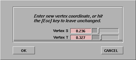
The Texture Placement window displays a texture that is mapped to a surface, and allows you to position the texture interactively. The two dimensions of this window (S and T) represent the two parametric dimensions of the active surface (U and V). A texture mapped to the active surface is therefore displayed in the Texture Placement window relative to the surface.
Please note that not all texture parameters are available when using textures within Shapes when sketching or painting.
The buttons at the bottom of the Texture Placement window allow you to edit the position and orientation of the texture relative to the surface.
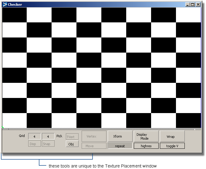
The title bar contains standard dolly and track icons, and full/half/resize, minimize, and close icons. The buttons and menus located along the bottom of the window let you interactively edit all Surface Placement and Label Mapping parameters. There are also some additional tools along the bottom of the window that are unique to the Texture Placement window.
The Grid buttons allow you to display a grid in the window, specify the size of the grid, and enable snapping of texture vertices to the grid.
Displays a light grey grid in the window. The numeric field above the Disp button controls the number of vertical grid lines (representing U in parametric space), and the numeric field above the Snap button controls the number of horizontal lines (representing V in parametric space). Click in either of these fields to change the number of grid lines.
Enables snapping of texture vertices to the nearest grid location when you perform texture vertex transformations.
The Pick buttons, Obj (Object) and TVert (Texture Vertices) allow to you to select geometry or vertices in the modeling window, and load them into the Texture Placement window. Picking geometry or vertices in the modeling window is similar to using the Pick > Point Types > CV tool:
tool:
| Mouse Button | Selection Description |
|---|---|

|
toggles selection |
|
|
deselects all vertices or geometry |

|
deselects vertex or geometry |
The Obj and TVert buttons are mutually exclusive; only one can be active at a time.
Allows you to select polygonal geometry in the modeling window and load it into the Texture Placement window. You can modify geometry loaded into the Texture Placement window using the Transform tools.
If any polysets, components, or polygons are selected when you first open the Texture Placement window, all polysets or fully selected polygons are loaded (if all of their vertices are selected) into the Texture Placement window. This geometry is displayed as two-dimensional parametric space geometry. At any point after you open the window, you can change the loaded geometry by clicking the Obj button and selecting the geometry in the modeling window.
When the Obj button is selected, you can select polygonal geometry at the vertex level by clicking and dragging in the modeling windows
(for example, by using the Pick > Point Types > CV tool). Polygons are loaded into the Texture Placement window only if all of their vertices are selected.
If you have selected polygonal geometry before opening the Texture Placement window, the Obj button is selected by default and all Texture Placement window tools are enabled. If you have not selected polygonal geometry before opening the Texture Placement window, the Obj button is not selected and all Texture Placement window tools are disabled except for the Obj button. Selecting polygonal geometry as above enables the tools.
While using the Texture Placement window, if you select another continuous tool (such as Transform > Move ), all geometry is unloaded and the Obj button is deselected. If you select the Obj button again, you can reload all active geometry. This also exits from the continuous tool.
A continuous tool is one that remains active after you have selected it and used it to perform an action (for example, Transform > Move).
Allows you to select polyset vertices in the modeling window. These vertices correspond to the vertices displayed in the Texture Placement window. You can modify selected vertices using the Vertex tools in the Texture Placement window.
The Vertex tools let you interactively transform selected polyset vertices.
You can select vertices by several methods:
key and click-dragging a box around the vertices.
(Windows) or (Mac) key and clicking in the middle of the polygon. This includes all vertices that are shared with other polygons.
and  (Windows) or and
  (Mac) keys and clicking in the middle of the polygon. This does not include vertices that are shared with other polygons.
Lets you rotate selected vertices about the current pivot point in the Texture Placement window by clicking and dragging in the window. The pivot point is indicated by a small green circle in the Texture Placement window, and is in the bottom left corner of the window by default.
| Mouse Button | Move Direction |
|---|---|
|
|
clockwise |
|
|
counter-clockwise |
To move the pivot point, see Set Pivot.
Lets you scale selected vertices about the current pivot point in the Texture Placement window by clicking and dragging in the window. The pivot point is indicated by a small green circle in the Texture Placement window, and is in the bottom left corner of the window by default.
| Mouse Button or Direction | Scale Type or Direction |
|---|---|
|
|
non-proportional scale |
|
|
proportional scale |
|
|
along the S or T axis |
| right or up direction | scale up (larger) |
| left or down direction | scale down (smaller) |
Lets you smear selected vertices in the Texture Placement window by clicking and dragging in the window. Vertices closest to the mouse pointer are moved more than vertices further away from the mouse pointer.
Lets you move the pivot point (used during Scale and Rotate operations) by clicking and dragging in the Texture Placement window. The pivot point is indicated by a small green circle in the Texture Placement window, and is in the bottom left corner of the window by default.
To center the pivot point within the selected vertices, move the mouse pointer over the Texture Placement window and press the C key.
Applies any Translate, Coverage, Rotate, Offset, or Repeat values (set using either the Transform tools, or the actual parameters in the texture’s Control Window) to all vertices loaded in the Texture Placement window.
The texture coordinate that results from the transformation is calculated and then assigned to the appropriate texture vertices in the Texture Placement window. A system prompt also asks whether you want to reset the texture transform values before you confirm the operation. If you decide to reset, then the transformation values are set to their defaults.
The Freeze Transform tool is very useful when preparing texture coordinate data for export to systems that do not support advanced placement options such as Translate, Coverage, Rotate, Offset, and Repeat.
Undoes the last vertex transformation you performed. You can also select the Undo function by moving the mouse pointer over the Texture Placement window and press the U key.
Two other vertex tools are available only by your using hot keys in the Texture Placement window.
Scales the S value of the selected vertices by a factor of -1 around the center of the selected vertices (no matter where the pivot point is). This flips the vertices horizontally.
Scales the T value of the selected vertices by a factor of -1 around the center of the selected vertices (no matter where the pivot point is). This flips the vertices vertically.
The Transform tools let you transform the texture relative to the active surface it is mapped to. Any transformations you make using these tools are automatically updated in the texture’s Surface Placement and Label Mapping parameters. The origin of the texture is in the lower left corner of the window. The U parametric direction is horizontal, and the V parametric direction is vertical.
Lets you move the texture on the surface by clicking and dragging in the Texture Placement window. This tool controls the texture’s Utranslate and Vtranslate values.
Lets you reduce the coverage of the texture on the surface by clicking and dragging in the Texture Placement window. This tool controls the texture’s Ucoverage and Vcoverage values.
Lets you rotate the texture on the surface by clicking and dragging in the Texture Placement window. The texture is not actually rotated in the Texture Placement window. Instead, a white border representing the edges of the surface is rotated. This tool controls the texture’s Rotate value.
Lets you offset the texture’s position on the surface by clicking and dragging in the Texture Placement window. This tool controls the texture’s Uoffset and Voffset values.
Lets you change the number of times that the texture is repeated within the coverage area by clicking and dragging in the Texture Placement window. This tool controls the texture’s Urepeat and Vrepeat values.
This changes with shapes; Urepeat and Vrepeat become Uscale and Vscale, which represent the number of times the texture repeats over 100 pixels. So if Uscale is set to 2, the texture will repeat twice in the U direction every 100 pixels.
Undoes the last transformation.
Automatically fits the texture to the surface.
Dollies the display in the Texture Placement window so that the placement object (representing the surface) fills as much of the window as possible.
The Display Mode tools let you change the way the surface and texture are displayed in the Texture Placement window. The default display mode is Picture.
Displays the surface as a white outline, the texture as a red outline, and the grid as blue lines.
Displays the texture as a color image against the shader color, unless you are using an Transform function. During Transform operations, the display changes to Line Only mode. When the Transform operation is completed and the mouse button is released, the texture is displayed as a color image again.
Displays the texture as a color image at all times.
Displays the texture as a high resolution color image at all times. High Res. mode may be slower than other display modes.