 Command entry: Render Setup dialog
  Renderer panel Camera Effects rollout
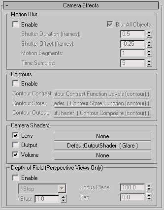
The controls in this rollout are for the camera effects depth of field and motion blur, as well as for contour shading and adding camera shaders.
To use depth of field for a Camera view:
For a Target camera, you can select the camera’s target object and move it. For a Free camera, you adjust the Target Distance on the Parameters rollout.
You might need to experiment with f-Stop values to get the effect you want.
To use depth of field for a Perspective view:
Camera Effects rollout, and in the Depth Of Field (Perspective Views Only) group, turn on Enable.
You might need to experiment with f-Stop values to get the effect you want. If you have trouble getting good results with f-Stop, use the drop-down list to change the method to In Focus Limits, then adjust the Near and Far values to enclose the region of the scene you want to be clearly in focus.
General panel, make sure that in the Motion Blur group, Enable is turned on and Object is chosen.
The mental ray renderer won't generate motion blur if Image is the chosen type.
Camera Effects rollout, and in the Motion Blur group turn on Enable.
Motion blur is not rendered when the mental ray renderer uses scanlines only.
The mental ray material also lets you assign a contour shader.
Renderer panel Camera Effects rollout, in the Contours group, turn on Enable.
To adjust the settings for a contour or camera shader assigned on this rollout:
 Open the Material Editor.
If you need to, arrange the open dialogs so you can see the Material Editor and the Render Setup dialog at the same time.
An Instance (Copy) Map dialog is displayed. Be sure to choose Instance, and then click OK.
If you don't choose Instance, changes you make to the shader settings in the Material Editor won't have any effect on the Render Setup dialog.
The Rendering Control Properties (lower-right) quad of the rendering quad menu (Ctrl+Alt+right-click) has a Motion Blur toggle for a single, selected object. You can turn on Motion Blur for lights and cameras: moving lights and cameras can generate motion blur when rendered with mental ray.
When on, the mental ray renderer calculates motion blur. Default=off.
When the scene uses motion blur, controls the number of times the material is shaded during each time interval (set by Shutter Duration). Range=0 to 100. Default=5.
By default, the material is shaded only once, and then blurred. If the material changes rapidly during the shutter interval, it might be useful to increase this value, in order to obtain more accurate motion blur. Rapid changes in reflections or refractions might require a higher Time Samples value.
Use Fast Rasterizer is on, the label for this parameter changes to Time Samples (Fast Rasterizer) to indicate that this version of Time Samples
is now in effect. The default value for the Fast Rasterizer version of Time Samples is 1, and the range is 1 to 128. If you
change the value for either version, 3ds Max remembers the changed setting when you switch.
These controls enable contours, and let you use shaders to adjust the results of a contour shader. You assign the primary contour shader to the Contour component of the mental ray Connection rollout or a mental ray material (see Advanced Shaders Rollout (mental ray Material)).
This component stores the data on which contours are based. It can be assigned the following shader, which has no parameters to set:
| Shader |
|---|
| Contour Store Function |
The contour output component can be assigned one of these shaders:
To adjust the settings for a shader assigned to one of these components, drag the shader's button to an unused Material Editor sample slot. When prompted to use an instance or a copy, be sure to choose Instance. (If you edit a copy of the shader, you will have to drag the sample slot back to the shader button on the Camera Effects rollout before you see any changes take effect.)
These controls let you assign mental ray camera shaders. Click a button to assign a shader to that component. After a shader is assigned, its name appears on the button. Use the toggle on the left to temporarily disable a shader that has been assigned.
Click to assign a camera output shader. These are the output shaders you can assign:
| Shader |
|---|
| Glare (The default.) |
| HDR Image Motion Blur |
| Motion Vector Export |
| Shader List (Output) |
Click to assign a volume shader to the camera. These are the volume shaders you can assign:
| Shader |
|---|
| Beam |
| Material to Shader |
| Mist |
| mr Physical Sky |
| Parti Volume |
| Shader List (Volume) |
| Submerge |
Depth of Field (Perspective Views Only) group
These controls are comparable to the depth-of-field controls for cameras. They apply only to Perspective viewports. You can render depth-of-field effects for either Camera or Perspective views. Depth-of-field effects don’t appear when you render orthographic viewports.
For a Perspective view, use the controls in this group. For a Camera view, choose “Depth Of Field (mental ray)” as the multi-pass rendering effect, then adjust the f-Stop setting. See Depth of Field Parameter (mental ray Renderer).
When on, the mental ray renderer calculates depth-of-field effects when rendering a Perspective view. Default=off.
Lets you choose the method for controlling depth-of-field. Default=f-Stop.
In most cases, the f-Stop method is easier to use. The In Focus Limits method can help when the scale of objects in the scene makes it difficult to control depth of field using the f-Stop value alone.
When f-Stop is the active method, sets the f-stop for use when you render Perspective views. Increasing the f-Stop value broadens the depth of field, and decreasing the f-Stop value narrows the depth of field. Default=1.0.
The f-Stop can have a value less than 1.0. This is not realistic in terms of an actual camera, but it can help you adjust the depth of field for scenes whose scale does not use realistic units.
When In Focus Limits is the active method, these values set the range, in 3ds Max units, within which objects are in focus. Objects lose focus when they are closer than the Near value or farther than the Far value. These values are approximate, because the transition from in-focus to out-of-focus is gradual, not abrupt.
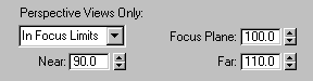
The Near and Far values are related to each other and to the value of Focus Plane. Changing the value of Near changes Far as well, and vice versa. Specifically, if
H = Hyperfocal distance, the Focus Plane value at which the Far limit becomes infinity


