Editable Spline provides controls for manipulating an object as a spline object and at three sub-object levels: vertex, segment, and spline.
The functions in Editable Spline are the same as those in the Edit Spline modifier. The exception is that when you convert an existing spline shape to an editable spline, the creation parameters are no longer accessible or animatable. However, the spline's interpolation settings (step settings) remain available in the editable spline.
When a spline-editing operation (typically, moving a segment or vertex) causes end vertices to overlap, you can use the Weld command to weld the overlapping vertices together or the Fuse command if you want the two overlapping vertices to occupy the same point in space but remain separate vertices.
 If you have several modifiers higher in the modifier stack, and want to see the results of edits in an Edit Spline modifier
or Editable Spline object, then turn on Show End Result on the Modify panel. As you edit the spline network, you’ll be able
to see the result of modifiers above the Editable Spline object. This is useful for Surface Tools work where you add a Surface
modifier above an Editable Spline object in the modifier stack.
If you have several modifiers higher in the modifier stack, and want to see the results of edits in an Edit Spline modifier
or Editable Spline object, then turn on Show End Result on the Modify panel. As you edit the spline network, you’ll be able
to see the result of modifiers above the Editable Spline object. This is useful for Surface Tools work where you add a Surface
modifier above an Editable Spline object in the modifier stack.
To produce an editable spline object, first select the shape, and then do one of the following:
 Convert to Editable Spline from the Transform (lower-right) quadrant of the quad menu.
Modifier Stack Result.
Convert to Editable Spline from the Transform (lower-right) quadrant of the quad menu.
Modifier Stack Result.
You can also right-click the object in the viewports and choose a sub-object level from the quad menu: Tools 1 (upper-left)
quadrant Sub-objects Choose the sub-object level.
Because sub-object selections can be complex, you might consider using one of the following techniques to prevent clearing the sub-object selection by accident:
To clone sub-object selections:
You can clone segment and spline sub-objects, but not vertices.
Notice that with Connect Copy on, new splines are drawn between the locations of the segment and its clone.
The following controls are available at the object (top) level and at all sub-object levels.
Rendering and Interpolation rollouts
These creation parameters appear in these rollouts for editable splines. For splines to which the Edit Spline modifier has been applied, creation parameters are available by selecting the object type entry (for example, Circle or NGon) at the bottom of the modifier stack.
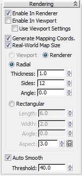
Controls here let you turn on and off the renderability of the shape, specify its thickness in the rendered scene, and apply mapping coordinates. The spline mesh can be viewed in the viewports. You can animate the render parameters, such as the number of sides. Viewport settings cannot be animated.
You can also convert the displayed mesh into a mesh object by applying an Edit Mesh modifier or converting to an Editable Mesh. The system will use the Viewport settings for this mesh conversion if Use Viewport Settings is turned on; otherwise it will use the Renderer settings. This gives maximum flexibility, and will always give the conversion of the mesh displayed in the viewports.
Controls the scaling method used for texture mapped materials that are applied to the object. The scaling values are controlled by the Use Real-World Scale settings found in the applied material's Coordinates rollout. Default=off.
Displays the 3D mesh as a cylindrical object.
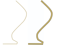
Splines rendered at thickness of 1.0 and 5.0, respectively
Displays the spline's mesh shape as rectangular.
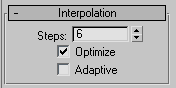
The Interpolation controls set how 3ds Max generates a spline. All spline curves are divided into small straight lines that approximate the true curve. The number of divisions between each vertex on the spline is called steps. The more steps used, the smoother the curve appears.

Splines used in above lathed objects contained two steps (left) and 20 steps (right)
Use the Steps field to set the number of divisions, or steps, 3ds Max uses between each vertex. Splines with tight curves require many steps to look smooth while gentle curves require fewer steps. Range=0 to 100.
Spline steps can be either adaptive or manually specified. The method used is set by the state of the Adaptive check box. The main use for manual interpolation is to create splines for morphing or other operations where you must have exact control over the number of vertices created.
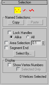
Provides controls for turning different sub-object modes on and off, working with named selections and handles, display settings, and information about selected entities.
When you first access the Modify panel with an editable spline selected, you're at the Object level, with access to several functions available as described in Editable Spline (Object). You can toggle the sub-object modes and access relevant functions by clicking sub-object buttons at the top of the Selection rollout.
You can work with parts of shapes and splines using shape sub-object selection of the Editable Spline object. Clicking a button here is the same as selecting a sub-object type in the Modifier List. Click the button again to turn it off and return to object selection level.
Any handle you move affects all handles in the selection, regardless of whether they're broken. This option is also useful when working with a single Bezier Corner vertex when you want to move both handles.
Shift+click a handle to "break" the tangent and move each handle independently. The Alike option must be chosen to break the tangent.
Lets you select automatically all vertices within a specific radius of the vertex you click. At the Vertex sub-object level, turn on Area Selection, and then set the radius with the spinner to the right of the Area Selection check box. This is useful when moving vertices that have been created using Connect Copy or Cross Section button.
Select a vertex by clicking a segment. In Vertex sub-object, turn on and select a segment close to the vertex that you want selected. Use this when there are a number of coincident vertices and you want to select a vertex on a specific segment. The cursor changes to a cross when it is over a segment. By holding down the Ctrl key you can add to the selection.
At the bottom of the Selection rollout is a text display giving information about the current selection. If 0 or more than one sub-object is selected, the text gives the number selected.
At the Vertex and Segment sub-object levels, if one sub-object is selected, the text gives the identification numbers of the current spline (with respect to the current object) and of the current selected sub-object. Each spline object contains a spline number 1; if it contains more than one spline, the subsequent splines are numbered consecutively higher.
When a single spline is selected at the Spline sub-object level, the first line displays the identification number of the selected spline and whether it's open or closed, and the second line displays the number of vertices it contains. When more than one spline is selected, the number of splines selected is displayed on the first line, and the total number of vertices they contain is displayed on the second line.
The Geometry rollout provides functions for editing a spline object and sub-objects. The functions available at the spline object level (when no sub-object level is active; see Editable Spline (Object)) are also available at all sub-object levels, and work exactly the same at each level. Other functions are also available, depending on which sub-object level is active. Those that apply to other sub-object levels are unavailable.
The functions available at the editable spline object level (that is, when no sub-object level is active) are also available at all sub-object levels, and work exactly the same at each level.
While at the Editable Spline (Vertex) level, you can select single and multiple vertices and move them using standard methods.
A segment is the portion of a spline curve between two of its vertices. While at the Editable Spline (Segment) level, you can select single and multiple segments and move, rotate, scale or clone them using standard methods.
While at the Editable Spline (Spline) level, you can select single and multiple splines within a single spline object and move, rotate, and scale them using standard methods.


 Modify panel
 Vertices
 Segments
 Splines