The functions available at the editable spline object level (that is, when no sub-object level is active) are also available at all sub-object levels, and work exactly the same at each level.
Rendering, Interpolation, and Selection rollouts
See the Editable Spline topic for information on the Rendering and Interpolation rollouts, and Selection rollout settings.
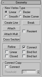
The radio buttons in this group let you determine the tangency of the new vertices created when you Shift+Clone segments or splines. If you later use Connect Copy, vertices on the splines that connect the original segment or spline to the new one will have the type specified in this group.
This setting has no effect on the tangency of vertices created using tools such as the Create Line button, Refine, and so on.
Adds more splines to the selected spline. These lines are separate spline sub-objects; create them in the same way as the line spline. To exit line creation, right-click or click to turn off Create Line.
Lets you attach another spline in the scene to the selected spline. Click the object you want to attach to the currently selected spline object. The object you're attaching to must also be a spline.
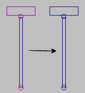
Unattached splines (left) and attached splines (right)
When you attach an object, the materials of the two objects are combined in the following way:
Attached shapes lose their identity as individual shapes, with the following results:
Any edits, modifiers, and animation applied to the attached shape are frozen at the current frame.
Creates a spline cage out of cross-sectional shapes. Click Cross Section, select one shape then a second shape, splines are created joining the first shape with the second. Continue clicking shapes to add them to the cage. This functionality is similar to the Cross Section modifier, but here you can determine the order of the cross sections. Spline cage tangency can be defined by choosing Linear, Bezier, Bezier Corner or Smooth in New Vertex Type group.
Inserts one or more vertices, creating additional segments. Click anywhere in a segment to insert a vertex and attach the vertex to the mouse. Optionally move the mouse and then click to place the new vertex. Continue moving the mouse and clicking to add vertices. A single click inserts a corner vertex, while a drag creates a Bezier (smooth) vertex.
Right-click to complete the operation and release the mouse. At this point, you're still in Insert mode, and can begin inserting vertices in a different segment. Otherwise, right-click again or click Insert to exit Insert mode.


 Modify panel