Command entry:
Select an editable spline


Modify panel
Expand the editable spline in the stack display
Segment sub-object level
Command entry:Select an editable spline
Modify panel
Selection rollout
Segment button
Command entry:Select an editable spline
Right-click the spline
Tools 1 (upper-left) quadrant of the quad menu
Sub-objects
Segment
A segment is the portion of a spline curve between two of its vertices. While at the Editable Spline (Segment) level, you
can select single and multiple segments and move, rotate, scale or clone them using standard methods.
Procedures
To change segment properties:
- Select an editable spline segment, and then right-click.
- On the Tools 1 (upper-left) quadrant of the quad menu, choose Line or Curve.
The effect of changing segment properties varies according to the type of vertices at the segment end.
- Corner vertices always result in line segments regardless of the segment property.
- Smooth vertices can support both line or curve segment properties.
- Bezier and Bezier Corner vertices apply their tangent handles only to curve segments. Tangent handles are ignored by line
segments.
- A tangent handle associated with a line segment displays an X at the end of the handle. You can still transform the handle,
but it has no effect until the segment is converted to a curve segment.
TipIf you have problems transforming the handles, display the axis constraints toolbar and change the transform axis there.
Interface
Geometry rollout
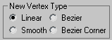
New Vertex Type group
The radio buttons in this group let you determine the tangency of the new vertices created when you Shift+Clone segments or splines. If you later use Connect Copy, vertices on the splines that connect the original segment or spline
to the new one will have the type specified in this group.
This setting has no effect on the tangency of vertices created using tools such as the Create Line button, Refine, and so
on.
_____
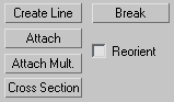
- Create Line
-
Adds more splines to the selected spline. These lines are separate spline sub-objects; create them in the same way as the
line spline. To exit line creation, right-click or click to turn off Create Line.
- Break
-
Lets you specify a break point at any segment in the shape (you do not have to first select a segment). When on, the mouse
icon changes to a Break icon. You can now click any spot on a segment. The clicked spot becomes two coincident vertices, and
the segment is split into two parts.
- Attach
-
Attaches another spline in the scene to the selected spline. Click the object you want to attach to the currently selected
spline object. The object you're attaching to must also be a spline.
For further details, see Attach.
- Reorient
-
Reorients the attached spline so that its creation local coordinate system is aligned with the creation local coordinate system
of the selected spline.
- Attach Mult.
-
Click this button to display the Attach Multiple dialog, which contains a list of all other shapes in the scene. Select the
shapes you want to attach to the current editable spline, then click OK.
- Cross Section
-
Creates a spline cage out of cross–sectional shapes. Click Cross Section, select one segment then another sub-object segment,
splines are created joining the first shape with the second. Continue clicking segments to add them to the cage. All segments
must be part of the same object to build cross sections. This functionality is similar to the Cross Section modifier, but
here you can determine the order of the cross sections. Spline cage tangency can be defined by choosing Linear, Bezier, Bezier
Corner or Smooth in New Vertex Type group.
TipWhen you want to move these vertices, turn on Area Selection before you select them. When you transform them, the vertices
will stay together.
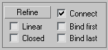
Refine group
The Refine group includes a number of functions useful for building spline networks for use with the Surface modifier.
- Refine
-
Lets you add vertices without altering the curvature values of the spline. Click Refine, and then select any number of spline
segments to add a vertex each time you click (the mouse cursor changes to a "connect" symbol when over an eligible segment).
To finish adding vertices, click Refine again, or right-click in the viewport.
You can also click existing vertices during a refine operation, in which case 3ds Max displays a dialog asking if you want to Refine or Connect to the vertex. If you choose Connect, 3ds Max will not create a vertex: it simply connects to the existing vertex.
The Refine operation creates a different type of vertex depending on the types of vertices on the endpoints of the segment
being refined.
- If the bordering vertices are both Smooth types, the Refine operation creates a Smooth type vertex.
- If the bordering vertices are both Corner types, the Refine operation creates a Corner type vertex.
- If either of the bordering vertices is a Corner or Bezier Corner, the Refine operation creates a Bezier Corner type.
- Otherwise, the operation creates a Bezier type vertex.
- Connect
-
When on, creates a new spline sub-object by connecting the new vertices. When you finish adding vertices with Refine, Connect
makes a separate copy of each new vertex and then connects all of the copies with a new spline.
NoteFor Connect to work, you must turn it on before you click Refine.
After turning on Connect and before beginning the refinement process, turn on any combination of these options:
- When on, makes all segments in the new spline linear by using Corner vertices. When Linear is off, the vertices used to create
the new spline are of the Smooth type.
- Causes the first vertex created in a refinement operation to be bound to the center of the selected segment.
For more information, see Bound Vertex.
- When on, connects the first and last vertices in the new spline to create a closed spline. When Closed is off, Connect always
creates an open spline.
- Causes the last vertex created in a refinement operation to be bound to the center of the selected segment.
For more information, see Bound Vertex.
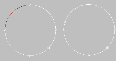
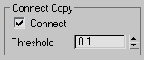
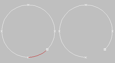
Connect Copy group
- Connect Copy
-
When on, Shift+cloning a segment creates a new spline sub-object with additional splines that connect the new segment's vertices to the
vertices of the original segment. It is analogous to Shift+cloning edges in Editable Mesh and Editable Poly objects.
NoteFor Connect Copy to work, you must turn it on before you Shift+Clone.
- Threshold
-
Determines the distance soft selection will use when Connect Copy is on. A higher threshold results in more splines being
created; a lower threshold results in fewer splines.
End Point Auto-Welding group
- Automatic Welding
-
When Automatic Welding is turned on, an end point vertex that is placed or moved within the threshold distance of another
end point of the same spline is automatically welded. This feature is available at the object and all sub-object levels.
- Threshold
-
The threshold distance spinner is a proximity setting that controls how close vertices can be to one another before they are
automatically welded. Default=6.0.
_____
- Insert
-
Inserts one or more vertices, creating additional segments. Click anywhere in a segment to insert a vertex and attach the
mouse to the spline. Then optionally move the mouse and click to place the new vertex. Continue moving the mouse and clicking
to add vertices. A single click inserts a corner vertex, while a drag creates a Bezier (smooth) vertex.
Right-click to complete the operation and release the mouse. At this point, you're still in Insert mode, and can begin inserting
vertices in a different segment. Otherwise, right-click again or click Insert to exit Insert mode.
_____
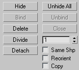
- Hide
-
Hides selected segments. Select one or more segments, and then click Hide.
- Unhide All
-
Displays any hidden sub-objects.
- Delete
-
Deletes any selected segments in the current shape.
- Divide
-
Subdivides the selected segment or segments by adding the number of vertices specified by the spinner. Select one or more
segments, set the Divisions spinner (to the button's right), and then click Divide. Each selected segment is divided by the
number of vertices specified in the Divisions spinner. The distance between the vertices depends on the segment's relative
curvature, with areas of greater curvature receiving more vertices.
- Detach
-
Lets you select several segments in various splines and then detach them (or copy them) to form a new shape. Three options
are available:
- (Same Shape) When on, Reorient is disabled, and a Detach operation keeps the detached segment as part of the shape (rather
than producing a new shape). If Copy is also on, you end up with a detached copy of the segment in the same location.
- The detached segment copies the position and orientation of the source object's creation Local coordinate system. The new
detached object is moved and rotated so that its Local coordinate system is positioned and aligned with the origin of the
current active grid.
- Copies the detached segment rather than moving it.
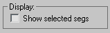
Display group
- Show selected segs
-
When on, any selected segments are highlighted in red at the Vertex sub-object level. When off (the default), selected segments
are highlighted only at the Segment sub-object level.
This feature is useful for comparing complex curves against each other.
Surface Properties rollout
Material group
You can apply different material IDs to spline segments (see Material ID). You can then assign a multi/sub-object material to such splines, which appears when the spline is renderable, or when used for lathing or extrusion. Be sure to turn on Generate
Material IDs and Use Shape IDs when lofting, lathing or extruding.
- Set ID
-
Lets you assign a particular material ID number to selected segments for use with multi/sub-object materials and other applications.
Use the spinner or enter the number from the keyboard. The total number of available IDs is 65,535.
- Select ID
-
Selects the segments or splines corresponding to the Material ID specified in the adjacent ID field. Type or use the spinner
to specify an ID, then click the Select ID button.
- Select By Name
-
This drop-down list shows the names of sub-materials if an object has a Multi/Sub-object material assigned to it. Click the
drop arrow and select a material from the list. The segments or splines that are assigned that material are selected. If a
shape does not have a Multi/Sub-Object material assigned to it, the name list will be unavailable. Likewise, if multiple shapes
are selected that have an Edit Spline modifier applied to them, the name list is inactive.
- Clear Selection
-
When turned on, selecting a new ID or material name forces a deselection of any previously selected segments or splines. When
turned off, selections are cumulative so new ID or material name selections add to a previous selection set of segments or
splines. Default=on.