mental ray Render Options Property Editor


| Rendering | Render Type

Defines how your scene will render using the mental ray renderer. You can control the rendering method, sampling, effects, and optimization.

To Display (do one of the following):

Rendering

Primary Rays

Type

Raytracing: Activates the raytracing rendering algorithm. If this option is selected, reflections and refractions can be rendered. If this option is deselected, transparencies that do not refract rays still work, as do environment maps.

Scanline: Activates the scanline rendering algorithm, which is faster than raytracing but gives less realistic results. When the scanline option is selected:

  • Reflection rays cannot be cast and refraction rays are computed as transparency rays.

  • Lens shaders cannot alter ray origin and direction.

  • A faster scanline motion blur is used, as opposed to a full ray traced motion blur with shadows.

  • You can create shadow-mapped shadows but not raytraced shadows.

Rasterizer: Optimizes motion blur rendering in scenes with a lot of motion blur. Setting the renderer type to Rasterizer provides you with special Sampling options discussed in the Motion Steps option group.

Sampling/Aliasing

Unified Sampling

Activates unified sampling. Unified sampling provides a new sampling method with simple and consistent controls for all rendering algorithms.

When this option is on, the Sampling controls are available.

When this option is off, the older sampling methods are used for the different algorithms. Use the Aliasing (Raytracing & Scanline Only) and Sampling Contrast settings to control the result.

Sampling

These controls are available only when Unified Sampling is enabled. Unified sampling provides simple and consistent controls for all rendering algorithms. The number of samples taken for any pixel is always between Minimum and Maximum. The exact value within this range is determined mainly by Quality. You can also set Cutoff to stop taking more samples if the difference between sample levels is smaller than the cutoff value.

Minimum

The minimum of samples per pixel. The minimum number of samples is always taken, regardless of Quality and Cutoff.

A value of 1.0 means at least 1 sample per pixel. Higher values cause oversampling, and lower values enable undersampling.

This value is not used with the Rasterizer algorithm.

Maximum

The maximum number of samples per pixel. If the specified number of samples is reached then no more samples are taken, regardless of Quality and Cutoff.

A value of 1.0 means at most 1 sample per pixel. Higher values enable oversampling, and lower values cause undersampling.

This value corresponds to Pixel Samples when using the Rasterizer algorithm.

Quality

Controls the number of samples in the range between Minimum and Maximum. It is a relative measurement — the higher the error in an area, the more samples get taken. Typical values are between 0.0 and 1.0 but larger values can be set.

This value corresponds to Shading Samples when using the Rasterizer algorithm.

Cutoff

The sampling error threshold. If the difference between sample levels is less than this value, no further samples are taken even if the number of samples set by Quality or Maximum hasn't been reached yet. This can be useful for increasing performance in dark, flat areas while not affecting quality in bright, detailed areas.

This value is not used with the Rasterizer algorithm.

Aliasing (Raytracing & Scanline Only)

Min Level

Specifies the minimum sample rate. When 0, every pixel is sampled at least once. The default is -1 (which gives one sample for a square 2 pixels by 2 pixels). If the value is too small, tiny features may be lost if the sample misses them. Set Min Level to -1 or greater to use the filters.

Max Level

Specifies the maximum sample rate. This sets the number of points within a pixel to be calculated and averaged to set that pixel's color. The default is 1 (a square 2-subpixels-by-2-subpixels within each pixel). Set Max Level to 1 or greater to use the filters.

Motion Samples

Specifies the number of motion samples to take for each color sample.

For more information, see Aliasing [Rendering].

Sampling Contrast

Sampling Contrast

The Red, Green, Blue, and Alpha sliders set the contrast thresholds on a per-channel basis for the adaptive supersampling method. If the contrast between adjacent sample areas is greater than the color R, G, B, A values, the area is divided and resampled until the Max Level value is reached.

Typical values are 0.1 for R, G, B, and A. Values such as 0.2 or 0.3 reduce quality and lower values increase quality. Values less than 0.05 do not further increase quality in most cases. R, G, B, and A can be specified separately to allow for physiologically correct contrast values; the human eye is much more sensitive to different shades of green than blue and red, and can only poorly distinguish shades of blue. The A value should be set to 1.0 if the matte (alpha) channel is not needed. It is also possible to set A lower than R, G, B to generate matte channels with a higher quality than the color image.

Note that for high-quality rendering, the Min and Max Level parameters must be adjusted. The rasterizer does not use the Sampling Contrast or the Min/Max Level settings.

For more information, see Sampling Contrast and Antialiasing, Sampling, and Filtering Tips & Tricks [Rendering].

Rasterizer

Shading Samples

Specifies how many samples to use (per-pixel) to draw the triangles into which surfaces are subdivided.

Set the Shading Samples to control the size of the tessellated primitive with respect to view dependent tessellation. Essentially, this value is the number of triangles per pixel. Since each triangle has one shading sample, this represents the number of shading samples per pixel for each layer of intersection. If all the objects were opaque, the total shading samples for a scene would equal approximately this number times the number of pixels. The Shading Samples default of 4 would be four triangles per pixel. Quality increases as the value increases above 1.

  • For motion blurred scenes, a setting of 5 or 6 is usually sufficient.

  • For static scenes, or scenes where the surface sampling results in triangles no smaller than one pixel, a setting of 1 is adequate.

When Unified Sampling is enabled, use the Quality setting in the Sampling group instead.

Pixel Samples

Adjust the Pixel Samples to specify the number of samples used per pixel to draw the subdivided triangles. The equation for determining how many samples are taken per pixel is n x n, where n is the number specified for this option. For example, the default value of 4 gives 16 samples per pixel.

Pixel samples defined along the pixel edge equals 1

Pixel samples defined along the pixel edge equals 2

For motion-blurred objects, this means the number of samples that are used per rendered pixel, since the object may or may not be in the pixel when the pixel is sampled at a given time.

When Unified Sampling is enabled, use the Maximum setting in the Sampling group instead.

Motion Samples

Set the Motion Samples to allow for more than one shading sample over the frame time per triangle. This option specifies how many times a shading sample is taken during the open shutter interval. This means that each moving triangle stores this many shading samples.

The sample is taken at times 0, 1/n, .., n-1/n, where n is the value specified for this option.

Note that multiple shading samples can be used to cut down on artifacts produced, for example, when blurred, reflective objects "drag" their fixed reflection across the motion. Shading samples act as oversampling for anything that changes over time during the shading process.

Motion Factor

Sets an automatic factor for tweaking the shading samples such that a lower shading frequency is used the faster the object is moving.

A value larger than 0.0 automatically lowers shading samples for fast-moving objects, at a rate proportional to the magnitude of the setting and the speed of the objects. A value of 1.0 should provide a good starting point. Setting this value to 0.0 (the default) disables this feature.

Max Depth

Sets the maximum depth to which the rasterizer will composite shading samples. This can be used to speed up hair rendering and scenes where it is known that many subsequent samples, further away from the camera, do not contribute as much to the final pixel as the first few.

If set to a positive value the rasterizer will end the transparency compositing at the depth specified. Setting this value to 0.0 (the default) does not impose any limit.

For more information about optimizing motion blur rendering, see The Rasterizer [Cameras and Motion Blur].

Motion Steps

Transform

Transformation motion blur is calculated based on a linear interpolation between an object's motion data at the beginning and end of the shutter time. Increasing the interpolation value adds extra steps between these two points, and interpolates linearly between successive steps. This improves the blurred result considerably for rotating objects. The Interpolation Steps value cannot exceed 15.

Deformation

Deformation motion blur is calculated based on a curvilinear interpolation between an object's motion data at the beginning and end of the shutter time. Increasing the interpolation value adds extra steps between these two points, and creates curved motion between each successive interpolation step. This improves the blurred result considerably for animated deformations. The interpolation steps are placed randomly (using the Quasi-Monte Carlo method) along the object's motion data. The Deformation slider allows values between 1 and 8. You can enter higher values manually, but you cannot exceed 15. Keep in mind that any value greater than 8 will significantly impact rendering time.

Enabled Features

The Enabled Features options allow you to toggle various types of shaders in order to achieve faster preview rendering. By default, all shader types are enabled. Types that you deactivate are ignored.

For more information on shaders and how to use them, see The Shader Library.

Geometry Shaders

Activates procedural geometry shaders.

Displacement Shaders

Activates Displacement shaders.

Lens Shaders

Activates Lens shaders. Used when a primary ray is cast by the camera. They may modify the ray's origin and direction to implement cameras other than the standard pinhole camera, and they may modify the result of the primary ray to implement effects such as lens flares.

Volume Shaders

Activates Volume shaders. Used to modify rays as they pass through an object to simulate effects such as clouds, smoke, and fire.

Output Shaders

Activates Output shaders. Operates on rendered images before they are written to a file and perform operations such as filtering, compositing with other files, and writing to different file formats.

Hair Geometry

Enables geometry hair rendering in the current pass.

For more information about rendering hair, see Rendering Hair [Hair].

Lightmaps

Activates Lightmap shaders.

Optimization

Render Type

Render Type

  • Full Render: renders the scene according to the complete set of rendering options

  • Lightmaps Only: renders only the lightmaps required for the lightmap shaders used by the scene.

  • Final Gathering Only: generates only the final gathering maps required by the scene. For more information about final gathering maps, see Final Gathering [Indirect Illumination].

  • Photon Maps Only: generates only the photon maps required for the scene. For more information about photon maps, see Global Illumination and Caustics [Indirect Illumination].

For Heavy Scenes

Optimize

Automatically sets parameters for heavy scene optimization. See Optimizing Large Scenes for Scalability [Rendering].

Restore Defaults

Resets heavy scene optimization parameters to their default values.

Primary Rays

Quick access to the same rendering algorithms specified on the Rendering tab.

[type]

Raytracing: Activates the raytracing rendering algorithm. If this option is selected, reflections and refractions can be rendered. If this option is deselected, transparencies that do not refract rays still work, as do environment maps.

Scanline: Activates the scanline rendering algorithm, which is faster than raytracing but gives less realistic results. When the scanline option is selected:

  • Reflection rays cannot be cast and refraction rays are computed as transparency rays.

  • Lens shaders cannot alter ray origin and direction.

  • A faster scanline motion blur is used, as opposed to a full ray traced motion blur with shadows.

  • You can create shadow-mapped shadows but not raytraced shadows.

Rasterizer: Optimizes motion blur rendering in scenes with a lot of motion blur. Setting the renderer type to Rasterizer provides you with special Sampling options.

Memory Limit (mental ray)

Activating the Memory Limit allows you to specify how much virtual memory mental ray can use to render your scene. When this setting is deactivated, no memory limit is set.

Enable

Activates a limit on the amount of RAM used for rendering.

Limit (MB)

Sets the memory limit to the value that you specify in megabytes.

Secondary Rays - Depth

You can control whether reflection and refraction are rendered by enabling secondary rays. When secondary rays are active, you may need to adjust the Secondary Rays - Depth settings to accommodate the amount of reflection or refraction in the scene.

Depth refers to the number of times that a ray is reflected or refracted during the raytracing process. Each refraction or reflection of a ray creates a new branch in a ray tree.

Use higher values for a more accurate image, or use lower values for preview renders or to speed up rendering in scenes with little reflection or refraction.

Enabled

Activates secondary rays for reflection and refraction.

Reflection

Sets the maximum number of a ray's reflective branches in a scene. For example, in a totally reflective scene, the ray continuously bounces around in the scene creating an infinite number of branches. This option lets you set an upper limit on these calculations.

Refraction

Sets the maximum number of times a ray can be refracted in a scene. For example, on an object with few smooth sides and a high refractive value, the refraction ray continuously bounces around the scene creating an infinite number of branches. This option lets you set an upper limit on these calculations.

Combined

Sets an upper limit on the sum of a ray's reflections and refractions.

Tile Order

Each frame is rendered one tile at a time. You can set the size of the tiles, as well as the order in which they are rendered.

Order

The Tile Order specifies the order, or more accurately the pattern in which tiles are rendered. There are two possible settings:

  • Hilbert renders tiles in a pattern defined by a Hilbert curve. This is usually the preferable setting, particularly when rendering large meshes.

  • Spiral renders tiles from the center of the frame outward in a spiral pattern.

Tile Size

Each frame is rendered one tile at a time. You can set the size of the tiles, as well as the order in which they are rendered.

Size

Render Tile Size allows you to define the size of the tile used when rendering an image. Usually, you would use a smaller tile size when you are performing a distributed rendering that has a host and/or slaves operating at different speeds.

Assigning a smaller tile size avoids delaying the faster hosts/slaves by not making them wait for slower slaves that may be taking more time to render a large tile.

Geometry

Mesh Splitting Factor

At render time, Softimage splits large objects into many pieces, each of which can be computed separately. It then sends a minimal amount of object data to the mental ray renderer which, in turn, uses a system of callbacks to request only portions of the object that it needs.

The splitting factor affects the size (in triangles) and number of pieces that are created when the mesh is split. The default value of 1 splits a given mesh into the number of pieces that the underlying computations determine to be appropriate. Lowering the factor value to, say, 0.5 doubles the number of pieces, but halves their size.

For more information, see Mesh Splitting [Rendering].

Visible Geometry Side

By default, both faces of an object are rendered — those whose normals are facing the camera as well as those that are not. If you like, you can render just one face of an object. In this instance, the other face is "culled" (ignored).

For example, if you select Front, only the polygons facing the camera are rendered. You should select this option if the back faces of the object are not influential in the scene.

To ensure the highest–quality image, you should select Both. You should also make sure to select Both if you are rendering a double–sided transparent object.

  • Both: Renders both the front and back of an object.

  • Front: Renders only the front sides of objects (normals are facing the camera).

  • Back: Renders only the back sides of objects.

Sample Displacement Before Rendering

This option can help speed up displacement rendering by providing mental ray with the correct bounding boxes for its calculations.

The presampling increases the startup time when rendering the displaced object, but the actual rendering itself is much faster. The overall benefit can reach a performance factor of three. However, for quick previews when you want to get the first pixels as quickly as possible, regardless of the time it takes to complete the image, you may want to disable this option. The default is on.

When enabled, mental ray performs a rough displacement on the object before rendering in order to obtain a correct bounding box for its calculations. This is particularly helpful if the maximum displacement parameter is set very low. (Geometry Approximation > Displacement > Max. Displ.)

When disabled, mental ray takes the object's current bounding box (samples the original non-displaced mesh) and the maximum displacement, and uses that to decide whether or not the object is a part of a tile being rendered. In this case, if the maximum displacement is set too low, then you may end up with the object missing from some of the rendered tiles.

Motion-Based Displacement Quality

When set to a value greater than 0.0, this option allows you to automatically control the amount of displacement detail rendered on an object based on how fast the object is moving in screen space. The automatic reduction of displacement detail on moving objects has a significant impact on rendering performance and memory consumption by cutting down on the typically huge amount of tessellation data that gets generated.

The displaced geometry should have a geometry approximation property applied to it and motion blur must be enabled for the render region and/or the render pass. See Applying and Editing Geometry Approximation [Scene Elements] and Defining and Rendering Motion Blur [Cameras and Motion Blur].

For fast moving objects, you can set the motion-based displacement factor to achieve images of comparable visual quality with fewer displacement details as compared to static or slow moving objects.

Though it is possible to tweak displacement approximation on a per-object basis, this approach can be time-consuming and not very practical. In addition, the calculation of standard displacement approximation does not take into consideration that an object can have different amounts of motion across its different parts. Motion-Based Displacement Quality provides an automatic way of adjusting the displacement quality according to the amount of motion for a given object part. The geometry is reduced only in areas of the object with strong motion.

Setting this option to 0.0 turns off this feature and there is no reduction of displacement detail based on motion. A value of 1.0 is the default and results in an acceptable compromise between quality decrease and rendering acceleration. Values greater than 1.0 further reduce the displacement detail for a given unit of motion, and values less than 1.0 raise the quality towards the static case.

With a value of 1.0, the simplification of geometry takes effect for motion of approximately 16 pixels per frame. On slower moving objects, use higher values. For example, a value of 8 reduces the geometry in the areas of an object moving at the speed of 2 pixels per frame.

The Motion-Based Displacement Quality setting uses the minimum motion of each polygon under the displacement. For example, this displaced polygon mesh sphere was shape animated by moving one side of it 10 units to the left over ten frames. The series of images below show the results of Motion-Based Displacement Quality at 0, 2, 5, and 10. With a quality setting of 10, you'll notice only severe degradation of displacement quality of the polygons going at full speed (and not for the polygons that have zero speed on one vertex and high speed on others).

Motion-Based Displacement Quality = 0

Motion-Based Displacement Quality = 2

Motion-Based Displacement Quality = 5

Motion-Based Displacement Quality = 10

Shutter Settings

Shutter

You should first set the shutter Scene Render Options Property Editor for the scene to define the point in time when the geometry and its motion transformations and motion vectors are evaluated: this data is pushed to mental ray. See Scene Motion Blur Settings [Cameras and Motion Blur].

Once an appropriate shutter interval is set, you can then use the mental ray Shutter and Delay options to tweak the size and length of the motion blur trails (without re-evaluating the geometry and its motion data). These options allows you to quickly "dial-in" settings, if needed, although they are not particularly accurate.

A value of 1 for Shutter causes mental ray to use the full length of the geometry's motion transformations and motion vectors as specified by the Speed option for the scene.

Delay

A non-zero delay offsets the motion blur trails.

Convert Textures to Memory Maps

When a texture is memory-mapped, it means that the texture is never loaded into memory. Instead, it is accessed directly from disk whenever a shader uses it. When used properly, memory mapped textures can speed up rendering considerably.

The Convert Textures to Memory Maps options allow you to override the Rendering Preferences options for converting your image clips to memory mapped format at render time. For more information about working with memory-mapped images, see Using Memory-Mapped Textures [Texturing].

Rendering Preferences

Opens the Rendering Preferences [Preference Reference] so that you can view your settings.

[convert memory mapped]

Specifies whether images are converted to memory-mapped (.map) format at render time. Choose one of the following:

Use Preferences: converts images to .map format based on the preferences defined in the Rendering Preferences property editor.

Enabled: .map files are generated and used when you render the pass, regardless of whether or not automatic .map file conversion is activated in the rendering preferences.

Disabled: .map files are not generated when you render the pass, regardless of whether or not automatic .map file conversion is activated in the rendering preferences. Previously auto-generated .map files are not used when rendering the pass as long as you maintain this setting

Framebuffer

Sample Filtering

You can select a filter type for the post-rendering filter process that can be applied to the completed image. For each pixel, mental ray uses the values of the surrounding pixels to remove aliasing. The type of the filter determines how the surrounding pixels are weighted when calculating their average.

For more information, see Setting Sample Filtering [Rendering].

Filter Type

Selects a type of filter to use.

Box: Sums up all pixels in the filter area with an equal weight. This is the fastest type of filtering.

Triangle: Weights the pixels using a triangular distribution (peaked at the top).

Gaussian: Weights the pixels using a Gaussian bell-shaped curve. This filtering is best at controlling soft staircase effects.

Mitchell: Weights the pixels using a narrower bell-shaped curve than the Gaussian filter. The curve can go into negative values near the edges.

Lanczos: Weights the pixels using a narrower, less bell-shaped curve than the Gaussian or Mitchell filters. The curve can go into negative values near the edges.

Filter Size

Sets the size of the filter in pixels. X specifies the width and Y specifies the height. Larger values result in softer images. Typical values are 1 for Box filters, 2 for Triangle filters, 3 for Gaussian filters, and 4 for Mitchell and Lanczos filters.

Jitter Sub-pixel Samples

When enabled, the location of each sample is shifted from its calculated position. Varying sample locations can help reduce artifacts, particularly areas where small details might be lost between samples.

When disabled, there is no jitter; and samples are taken at pixel (or subpixel) corners.

Jitter does not affect render time very significantly.

Same Sampling Pattern on All Frames

When activated, the same sampling pattern is used for every rendered frame. This can help to reduce flickering caused by changes to the sampling pattern from frame to frame.

Color Control

The Color Control parameters allow you to activate various basic image processing options that are then performed during rendering. The following processes are available:

Premultiply with Alpha

Automatically multiplies an object's RGB values with their associated alpha value. This precomputation is helpful if you wish to composite the object image later on.

Dither 8-bit Framebuffers

Simulates colors in the image to create a smooth gradation between areas of light and dark resulting in a very low slope of color variation.

Desaturate colors when clipping

Specifies how colors whose values exceed the valid range, as defined by the Color Channel Clipping option, are clipped to within the valid range of 0 to 1.

If this option is disabled, colors are simply clipped to within the valid range of 0 to 1. If it is enabled, color values are reduce proportionally until they are within the valid range. The result is that the color's brightness is maintained.

Color Channel Clipping

The Color clipping option defines how colors are clipped to a 0 to 1 range if they are not being written at floating-point precision. In all modes, the RGB components are clipped as specified by the desaturate option. Both the RGB and Alpha modes ensure that the resulting color is a valid premultiplied color.

The following modes are available:

  • Clip alpha below RGB mode first clips RGB values to the 0 to 1 range, and then clips alpha values to the MaxRGB to 1 range. Use this mode when you need to preserve RGB color and intensity, but the alpha channel is less important.

  • Clip RGB above alpha mode, alpha is first clipped to the 0 to 1 range, and the RGB is clipped to the 0 to A range. This mode is useful for alpha compositing, since its is more important that the transparencies are correct and less important that RGB color and intensity are correct.

  • No Clip turns off color channel clipping.

Motion Data

Maximum Motion

Sets a cap on the motion vector data being output with any motion or raster motion channel. This value specifies the maximum length (measured in pixels) allowed for the motion vectors.

Compensate For Object Motion

When on, motion compensation dynamically adjusts the shutter offset and close values so that the object is placed at (or as close as possible to) the location where it would normally appear if there was no motion blur enabled. When off, there is no compensation and the object is always placed at the shutter close position.

This option only affects the on-frame shutter modes when rendering to motion or raster motion render channels. For details, see Scene Motion Blur Settings [Cameras and Motion Blur].

Advanced Settings

On-disk Framebuffers

When enabled, framebuffers are stored in framebuffer files on-disk to conserve memory. Framebuffer files are saved to your system's temporary folder as specified by the TEMPDIR or TEMP system environment variables. Framebuffer files are removed from disk when rendering is finished.

When disabled, framebuffers are kept in memory.

Sample contrast check on all color framebuffers

When outputting multiple framebuffers, mental ray evaluates all color (RGB) framebuffers before deciding to further subdivide the samples. It is recommended that you do not disable this option.

Shadows

Raytraced

Type

Activates Shadow shaders and allows you to select a shadow rendering method:

Disabled: Does not allow the light to compute shadows. This option is usually used to speed up rendering.

Enabled (regular shadows): Perform a basic, simple rendering of the shadows. The amount of light from a light source that passes through a shadow-casting object is determined. The shadow shaders are called in a random order.

Sorted: Similar to regular shadows but calls the shadow shaders differently. The shadow-casting objects are sorted so that the shadow shader of the object closest to the illuminated point is processed first and the object closest to the light is processed last.

Segmented: Also sorts the shadow shaders in a specific fashion. When Segmented is chosen, shadows are computed by tracing the segments (between the illumination point, the occluding objects and the light source) and applying volume shaders to these segments (shadow segments). This process slows down rendering but is required of volume effects are to cast shadows; for example, a fur shader.

Shadowmaps

Enable

Enables the use of shadow maps during a render.

Motion Blur

When on, shadow maps on motion blurred objects are rendered.

Ambient Occlusion

For more information, see Setting the Global Ambient Occlusion Options [Indirect Illumination].

Ambient Occlusion

Enable

A global switch for enabling or disabling all ambient occlusion computations.
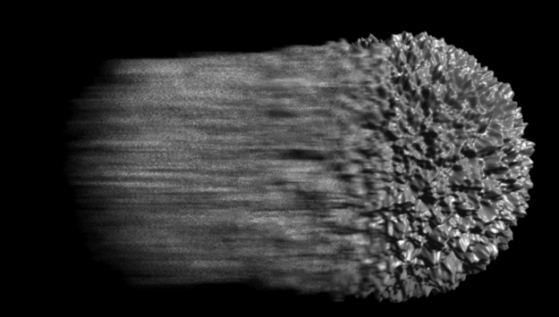
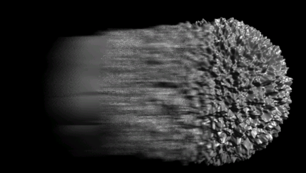
Number of Rays

When ambient occlusion is enabled, and the Number of samples is set to 0.0 in the Ambient Occlusion shader, then Rays is the value used for the number of rays to cast when computing the ambient occlusion at the current shading point. As long as the ambient occlusion shader has its Number of samples set to a positive non-zero value, then the Rays value is ignored.

Cache

Enable

Enables or disables the creation of the ambient occlusion cache. If caching is disabled, but ambient occlusion is turned on, then ambient occlusion is performed on demand only, when the ambient occlusion shader actually calls for the computing of ambient occlusion. Default is off.

Density

Sets the upper bound to the number of ambient occlusion points per pixel.

Points

The number of ambient occlusion cache points close to the lookup location that should be used for interpolation when the cache is enabled.

GPU Ambient Occlusion

Enable

Enables or disables the calculation of ambient occlusion in the GPU while Mental Ray is rendering to the main framebuffer on the CPU. It speeds up the Ambient Occlusion calculations by using the power of your GPU. Moreover, this speeds up workflows, which traditionally perform separate passes for ambient occlusion. By default, this option is turned off.

NoteThis GPU Ambient Occlusion requires a video card and driver that supports CUDA 4.2.

Number of Passes

Number of iterations for ambient occlusion. More number of iterations result in better quality, but slower computation. The recommended values are squared numbers (1, 2, 4, 9, and so on).

Falloff

Exponent

Parameter to control the falloff curve when calculating the ambient occlusion.

Start Distance

Parameter to specify when the falloff needs to start.

Maximum Distance

Maximum distance to take into account when calculating the ambient occlusion.

Output

Render Channel

The output rendering channel to store the results. To add a channel for GPU Ambient Occlusion, add a framebuffer to the current pass and select the GPUAmbientOcclusion channel from the Render Channel drop-down list.

Final Gathering

Final Gathering is another way mental ray can calculate global illumination without photons. It calculates both direct and indirect lighting, using rays cast from the object's pixels rather than from the light.

For more information about setting up for final gathering renders, see Final Gathering [Indirect Illumination].

Final Gathering

Enable

Turns final gathering on and enables the Final Gathering render options on this page.

Visualize

Preview

When each frame is rendered, the final gathering points and color are displayed in the render region or render window.

Accuracy

Depending on the final gathering mode you are working with you will need to set a combination of the following Accuracy options which are the main settings used to control the quality of a final gathering render.

For more information, see Setting Final Gathering Accuracy Options [Indirect Illumination].

Mode

Select a final gathering mode:

  • Multiframe mode targets rendering of camera fly-through animations. To avoid picking up illumination from distant objects which is possible in the Automatic mode, set the Max Radius option to limit the maximal distance, within which, if sufficient finalgather points are not found, the illumination is smoothly faded to black.

This mode is typically useful for animated scenes, but is not the best method for animation where flickering is not a problem. It can also be used for still images without animation.

The Accuracy parameters used to control this mode are the Number of Rays, the Max Radius, the optional View Dependent flag, and the finalgather Points used for the interpolation.

  • Automatic mode primarily targets rendering of single still images. The Accuracy parameters used to control this mode are the Number of Rays, the optional View Dependent flag, and the finalgather Points used for the interpolation.

  • Expert mode is provided for compatibility with version 3.4 of mental ray, and to give the experienced user more control over the final gathering computations. This mode typically gives results similar to those achieved in version 3.4 of mental ray, and makes use of all the finalgather Accuracy options (including max and min radii).

  • Legacy mode is similar to the Expert mode, but achieves higher compatibility with mental ray version 3.4, allowing re-rendering of scenes using mental ray version 3.5 or later. Some rendering improvements are disabled in this mode.

  • Exact mode bypasses the final gathering point cache entirely and computes the full final gathering solution for every sample, rather than interpolate between final gathering points. This takes time but will yield superior results. The only Accuracy parameter used to control this mode is the Number of Rays.

View Dependent

Specifies whether the Minimum and Maximum Radius values are measured in scene units or in pixels. The effect of activating this option is to cast fewer final gathering samples for objects that are farther from the camera.

Number of Rays

Defines how many rays are fired from each pixel to calculate the indirect illumination. Use low values to tweak the effect (around 10-30) and increase for the final render (>100).

Interpolation Options: Final gather points are expensive to compute for every illuminated point, so mental ray uses the cached values of existing final gather points for interpolation of any additional final gather points that may be required to complete the effect. Min Radius, Max Radius, and the number of final gather Points are the parameters used specifically for interpolating these additional final gather points. For more information, see Setting Radii and Points for Interpolation [Indirect Illumination].

Points

Available for Multiframe and Automatic final gathering modes.

The minimum number of precomputed final gathering points that are used for interpolation of the indirect illumination.

Max Radius

Available for Multiframe, Expert, and Legacy final gathering modes.

Max Radius defines the maximum distance in which a final gather result can be interpolated or extrapolated without spawning new rays. If there are too few final gather points within the Max Radius limit, then more final gather rays are shot and a new final gather point is computed.

Very low values (<1) will increase render times but yield higher quality renders.

Min Radius

Available for Multiframe and Automatic final gathering modes.

Min Radius defines the minimum distance within which a final gather result must be used for interpolation or extrapolation. It is normally set to 10% of the maximum radius.

Very low values (<1) will increase render times but yield higher quality renders.

Falloff

The Falloff options limit the length of final gathering rays to a distance of Stop in world space. If no object is found within a distance of Stop, the ray defaults to the environment color. The Start parameter defines the beginning of the linear falloff range. Any objects at a distance between Start and Stop will fade towards the environment color.

For more information, see Setting the Final Gathering Falloff [Indirect Illumination].

Enable

Activates the final gathering Falloff effect.

Using the Start and Stop values described below, falloff limits the effect of distant objects that are unlikely to have a significant impact on the surface color of scene objects. This increases rendering speed and reduces memory usage.

Start/Stop

The Start and Stop values affect final gathering rays as follows:

  • Results returned by final gathering rays whose lengths are less than or equal to the Start value are used normally.

  • Results returned by final gathering rays whose lengths exceed the Stop value automatically default to the environment color.

  • Results returned by final gathering rays whose lengths are between the Start and Stop values are attenuated with a linear falloff toward the environment color.

Advanced Options

Show

Displays or hides the advanced final gathering options. The advanced options are: Refinement Passes, Fast Lookup, Presample Density, Filter Size, Sampling Contrast, Maximum Sample Normal Deviation, Trace Depth, Primary Bounce Color, and Secondary Bounce Color.

The advanced options are hidden by default because they are infrequently used and in most cases their default settings work fine as is.

Refinement Passes

Enable

When enabled, Refinement Passes provide a progressive update (in three passes) of how the final gathering is being rendered. The passes are rendered using the mental ray Tile Size, instead of the usual final gathering tile order. Refinement Passes are most useful when used in conjunction with the final gathering Visualize option.

Fast Lookup

Irradiance from Photon Map

This option can be activated when you are using global illumination and final gathering together. When it is activated, irradiance information is stored for each photon location in the global illumination calculation. This means that you need fewer final gathering samples, and the final gathering calculations take less time. However, global illumination calculations will take longer.

Sampling Options

The Presample Density, sample Filter Size, and Sampling Contrast are options that can help to smooth out and fine-tune the final gathering effect to some extent, but they are not substitutes for tweaking the Falloff settings.

For more information, see Setting the Final Gathering Sampling Options [Indirect Illumination].

Presample Density

A multiplier for the number of final gathering points that are computed during pre-rendering.

Increasing this value can help to smooth out the final gathering effect a little bit, but is not a substitute for tweaking the settings.

Filter Size

Defines the range of the final gathering filter. The filter is designed to eliminate speckling by filtering out overly bright samples within the range.

Increasing the filter size grows the range as follows: If the filter size is set to 1, a given sample point is filtered using all of its neighboring sample points. Increasing the filter size to 2 adds those sample points, and their neighboring sample points, to the filter, and so on.

Higher values soften the contrast between neighboring final gathering samples and reduce speckling in the rendered frame. Setting the value to 0 disables filtering entirely, but may give better results when the number of final gathering rays setting is relatively low.

Sampling Contrast

Multiplies the final gathering color contribution to the scene. The overall effect is to brighten the rendered image, particularly where final gathering causes objects to "bleed" their colors onto one another.

Maximum Sample Normal Deviation

Degrees

Specifies how many degrees a final gathering point's surface normal can deviate from the sampling point's surface normal and still be used for interpolation when calculating the shading.

The default value of 25.842 degrees corresponds to the mental ray default and is equal to ArcCos(0.9).

The example scene below shows two geometric planes, with one lying flat on the XZ plane, and the other rotated 45 degrees downward. Both have local environment shaders, set to blue and red, respectively, which the final gathering sampling picks up.


When Maximum Sample Normal Deviation is set to 44 degrees, there is no interpolation of final gathering points where the blue and red planes join.


When Maximum Sample Normal Deviation is set to 45 degrees, the final gathering points will now interpolate where the blue and red planes join.

Trace Depth

These settings are similar to the Raytracing Depth settings, but apply only to final gathering rays. They specify the number of times a given ray is reflected or refracted.

For more information, see Setting the Final Gathering Trace Depth [Indirect Illumination].

Reflection

Specifies the maximum number of times a final gathering ray can be reflected in a scene.

Refraction

Specifies the maximum number of times a final gathering ray can be refracted in a scene.

Diffuse

Specifies the number of additional diffuse bounces for final gathering. For example, a value of 1 provides a single extra diffuse bounce, for a total of two bounces.

The overall effect of additional bounces is to brighten the final gathering effect, though the effect is somewhat more localized than the effect of increasing the final gathering Sampling Contrast (see Trace Depth.)

Combined

Specifies the number of times a final gathering ray can be reflected and/or refracted in a scene. The Combined value should not be less than the sum of the Reflection and Refraction values.

Primary Bounce Color

Bounces are defined by the Trace Depth Diffuse value. The irradiance part obtained from first bounce final gather is multiplied by this color. Note that this affects single bounces only (Diffuse value of 0).

Secondary Bounce Color

Bounces are defined by the Trace Depth Diffuse value. The irradiance part obtained from secondary bounce final gather is multiplied by this color. This color takes effect only when the Diffuse value is greater than 0, meaning that there is more than a single bounce.

Map File Settings

Defines how the final gathering map file is used.

[map file settings]

  • Overwrite existing file: computes final gathering points at each frame, and stores the results in a final gathering map file that overwrites any existing map file. In other words, the final gathering map is rebuilt at each frame.

  • Append new FG points to file: uses an existing final gathering map file, or calculates one for the first rendered frame. If mental ray computes additional final gathering points for subsequent frames at render time, these points are appended to the map file.

  • Only use FG points from file: uses an existing final gathering map (or calculates one for the first rendered frame), but does not append any new points computed at render time. After the initial computation, the map file is only modified if you change the final gathering Number of Rays value. This is useful for renderfarm setups where several machines may use the same final gathering map.

Final gathering calculations are based on the position of the pass camera. If you are using this option, make sure that the map file contains sufficient final gathering data for all camera positions in the rendered sequence.

Map File

Defines the name of the file to be used as a final gathering map. You can build the file name using Tokens and Templates.

Resolved Map File Path

Displays the fully resolved file name and output path for the final gather map. The map file name is appended to the scene output path defined in the Scene Render Options Property Editor.

GI and Caustics

Global Illumination

Enable

Enables Global Illumination rendering.

GI Accuracy

Accuracy is like a sampling parameter, which looks for a specified number of photons stored within the area defined by the Radius parameter. It defines the resolution of the photon map.

Once the photon map is calculated and displayed, you can then zoom, pan, or play back your animation in the render region using the precomputed map of the global illumination effect instead of computing the effect each time the render region is refreshed.

Photon Search Radius

Measured in SOFTIMAGE units, this parameter defines how far the renderer will search for photons in a scene.

Photon Merge Factor

Merges photons based on distance and the scene size. The higher the value, the more photons are merged, which can reduce flickering.

GI Photon Color

Global Illumination irradiance is multiplied by this color value to produce the final global illumination effect.

Setting the multiplier to intensity values greater than 1 brightens the global illumination effect. Setting a color tints the final effect.

Caustics

Enable

Activates the rendering of caustic lighting highlights. Caustic refers to light focused by a curved object through reflection or refraction. You must have caustics defined in your scene before activating it here.

Caustic Accuracy

Precomputes the caustic light effect. Once the photon map is calculated and displayed, you can then zoom, pan, or play back your animation in the render region using the precomputed map of the caustics instead of computing the caustic effect each time the render region is refreshed.

Photon Search Radius

Measured in SOFTIMAGE units, this parameter defines how far the renderer will search for photons in a scene.

Photon Merge Factor

Merges photons based on distance and the scene size. The higher the value, the more photons are merged, which can reduce flickering.

Sharpness Filter

Type

Selects a type of filter to use.

Box: Sums up all pixels in the filter area with an equal weight.

Cone: Weights the pixels using a triangular distribution (peaked at the top).

Gauss: Uses a bell-shaped distribution for weighting.

Size

Sets the size of the filter in pixels. Larger values result in softer images. Typical values are 1 for Box filters, 2 for Cone filters, and 3 for Gaussian filters.

Caustic Photon Filter

Caustics irradiance values are multiplied by this color value to produce the final caustic effect.

Setting the multiplier to intensity values greater than 1 brightens the caustics. Setting a color tints the final effect.

Irradiance Particles

For information on how to work with irradiance particles, see Irradiance Particles [Indirect Illumination].

Irradiance Particles

Enable

Enables irradiance particles to simulate indirect lighting.

Accuracy

For more information, see Setting Accuracy and Interpolation for Irradiance Particles [Indirect Illumination].

Indirect Passes

The number of additional passes of indirect lighting. When this option is greater than 0, a sequence of passes are done to collect the irradiance coming from every particle position, such that irradiance particles will contain both direct illumination and indirect illumination information. When this option is set to 0, then the irradiance particles will contain direct illumination information with one bounce of indirect lighting.

Rays

Specifies the number of rays shot while estimating the irradiance. The minimum is 2.

Intensity

The global scale factor for the intensity of the irradiance during rendering. This is a global tuning option for artistic control. It is specified as a single value (which is used to set R, G and B at once). The default is 1.0.

This option is not available when Final Gathering is enabled.

Indirect Passes Rays

The number of rays for each indirect pass.

Interpolation

These options are not available when Final Gathering is enabled.

When

This option is used to control the use of interpolation.

  • Never: Disables interpolation.

  • Always: Enables interpolate.

  • For Secondary Rays Only: Enables interpolation for secondary rays only. There is no interpolation for eye rays, but there is interpolation for reflections, refractions, etc.

Points

The number of points (nearest-neighbor) to use for the interpolation of indirect illumination.

Environment

For more information, see Storing Indirect Light from the Environment [Indirect Illumination].

Enable

Enables the use of environment maps for irradiance computation. When on, a separate particle map is built for the environment (if an environment shader is present) and used during rendering.

Rays

The number of rays used for the computation of irradiance coming from the environment map. This number can be much greater than the number of rays used for normal irradiance computation, especially if most of the environment is covered by scene geometry (for example, a typical case would be a room with just one or two windows). For outside scenes, a smaller number of rays should be adequate.

Intensity

The scaling factor for the irradiance contributed by the environment. This scaling factor is relative because it applies to the environment irradiance only: it may be further scaled if you specified a global scaling factor with the Accuracy Intensity option. If the environment intensity is set to 2.0 and the accuracy intensity is set to 3.0, then the actual scaling factor for the environment irradiance will be 6.0 (2.0 x 3.0).

Particle Map File

For more information, see Using the Irradiance Particle Map [Indirect Illumination].

[map file template]

Defines the name of the file to be used as a particle map. You can build the file name using Tokens and Templates.

Rebuild Map

Rebuild

When enabled, the particle map is recomputed at each frame. When off, mental ray will either read it from file or reuse the existing particle map (from a previous frame). The latter can be useful to avoid flicker in animation, such as with fly-throughs.

Note that the indirect illumination might become wrong if the camera or objects are moving. The particle map is essentially view dependent and it is possible that inaccuracies show up when there is movement.

Particle Map File Resolved Path

[map file resolved path]

Displays the fully resolved file name and output path for the particle map. The map file name is appended to the scene output path defined in the Scene Render Options Property Editor.

Photon Global

Indirect Illumination Algorithm

Global Illumination / Final Gathering

Specifies that global illumination photons and/or final gathering algorithms will be used to simulate indirect illumination.

Irradiance Particles / Final Gather

Specifies that irradiance particles algorithm will be used to simulate indirect illumination. Enabling irradiance particles automatically disables global illumination photons. Final gathering and caustic effects can still be defined in conjunction with irradiance particles.

When this option is selected, only the Density and Diffuse Bounces options are available below.

Importons

For information about importons in general, see Using Importon Maps [Indirect Illumination].

For more information about using importons with irradiance particles, see Storing Irradiance with Importons [Indirect Illumination].

Enable

Enables importon sampling. When enabled, the importons are emitted and the importon map is created.

When importons are being used with global illumination to optimize a photon map, the importons are discarded once the photon map is created.

Importons are automatically enabled when using the irradiance particles algorithm.

Density

Specifies the number of importons fired from the camera per pixel. The default and recommended value is 1.0.

The Density value can be lower than 1.0, in which case only a single importon is fired for a group of pixels. The minimal value for this option is 0.02, which results in approximately 1.0 importon per 50 pixels. Lower values will speed up importon emission, but may create a less optimal photon map and thereby decrease the final image quality (which defeats the purpose of enabling importons in the first place).

Merge Distance

Specifies the world-space distance used to merge importons closer than that distance. A value of 0.0 means that merging is disabled.

Diffuse Bounces

Sets the number of diffuse bounces the importons should scatter through. If set to 0.0, importons will not scatter on the diffuse bounces. This is the default.

In some cases it may be required to use more than a single diffuse bounce. This is often the case when global illumination is combined with final gathering, or when the Trace Through Geometry option is off.

Trace Through Geometry

When on, instead of stopping at the first opaque geometry and leaving an importon there, the importon tracing will carry on until it leaves the scene, leaving an importon at every geometry hit. This results in a significantly higher number of importons stored in the scene. However, it does smooth out any discontinuity in the distribution of the importons.

Note that his option is not available for irradiance particles. It is automatically disabled in order to avoid the proliferation of irradiance particles.

Trace Depth

The following options will increase render time significantly, but will yield better photon effects.

Combined

Sets an upper limit on the sum of a ray's reflections and refractions.

Reflection

Sets the maximum number of a ray's reflective branches in a scene. For example, in a totally reflective scene, the ray continuously bounces around in the scene creating an infinite number of branches. This option lets you set an upper limit on these calculations.

Refraction

Sets the maximum number of times a ray can be refracted in a scene.

Photon Volume Accuracy

The following options calculate global illumination within a volume, as defined by a volume shader.

Photon Volume Accuracy

Accuracy is like a sampling parameter, which looks for a specified number of photons stored within the area defined by the Radius parameter. It defines the resolution of the photon map.

Once the photon map is calculated and displayed, you can then zoom, pan, or play back your animation in the render region using the precomputed map of the global illumination effect instead of computing the effect each time the render region is refreshed.

Photon Search Radius

Measured in SOFTIMAGE units, this parameter defines how far the renderer will search for photons within a volume.

Photon Merge Factor

Merges photons based on distance and the scene size. The higher the value, the more photons are merged, which can reduce flickering.

Photon Map File

Map File Name

Defines the name of the file to be used as a Photon Map. If an invalid path is defined, the render will fail and abort. You can build the file name using Tokens and Templates.

Rebuild

When on, the Photon Map is recalculated at each rendered frame.

Diagnostics

Logged Messages

Log These Types of Messages

Controls the level of information/feedback provided during a rendering session. You can toggle any combination of the following options:

Errors outputs messages about missing .dll files, missing shaders, and other errors that may cause the render to abort.

Warnings outputs messages relating to problems that may cause the scene to render incorrectly.

Information outputs information computed for the scene, such as tessellated triangle counts, number of rays fired, and so on.

Progress outputs the percentage of the scene that has been rendered, and other information about rendering progress, such as when the render begins and ends.

Basic Debug outputs information about what information is computed and sent as each tile is rendered.

Detailed Debug outputs detailed information about what information is computed and sent as each tile is rendered.

Diagnostics

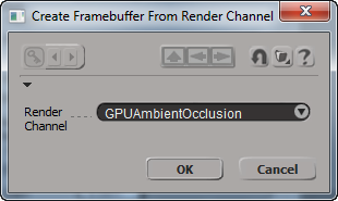
The following options allow you to render alternative representations of your scene that provide visual information about various parameters.

View Sampling

When on, the scene is rendered as a grayscale representation of Antialiasing sampling densities. The darker the region, the less it is sampled, and vice versa.

View Final Gather Points

When on, final gathering points are superimposed on the rendered image. Green points are those calculated during pre-processing, while red points are extra points, calculated at render time, to complete the final gathering effect.

View Photons

[map]

Specifies whether rendering the scene generates a color map of the red, green and blue photon irradiance components, or the photon density.

Maximum

This value acts as the max value for the diagnostic rendering. Areas where the photon density or irradiance matches this value are rendered in red. Areas with a higher density or irradiance value fade to white.

View Coordinate Grid

[space]

Specifies whether the diagnostic grid corresponds to object space, world space, or camera space. When one of these is selected, a colored grid, representing specified space coordinates, is drawn on all scene objects. Red, green, and blue lines represent steps in the X, Y, and Z axes respectively.

Size

Defines the size of each step in the grid.

Pixel Time Render Channel

Max Pixel Time (µS)

The upper bound or whitepoint of the pixel time values when shown in the render region or output to disk, in microseconds.

When displayed in the region, the image is shown in false color to show trouble spots better. Blue pixels have low values, green pixels have medium values, and red pixels have high values.

mi Archives

Defines how a scene will be exported to a render archive (*.mi2) or an object render archive (*.mia).

Write all cameras in archive

When on, all scene cameras are exported, rather than just the pass camera.

Write triangulated polygon surfaces

When on, the renderer exports tessellated polygons instead of the original geometry.

Write triangulated NURBS surfaces

When on, the renderer exports tessellated faces instead of the original surfaces.

Write ASCII data

Controls the format of vectors output to mi2 files. When on, vectors appear in the mi2 file as text; when off they appear in binary.

Embed textures in archive

Controls whether textures defined by path (Broadcast or Use from Disk) will be echoed as a path (Off) or binary texture data (On).

Use a geometry shader for subdivision surfaces

When on, only the unsubdivided meshes of subdivision surface objects are exported. A geometry shader is attached to each mesh to subdivide it at render time, using Softimage's system of split objects and render callbacks. This helps lower the size of the exported MI2 file.

When this option is off, subdivision surfaces are exported at their fully tessellated level.

Normally, this option should be left on unless you are rendering using the mental ray standalone on an operating system other than Windows or Linux, since other operating systems do not support this option.

Creative Commons License Except where otherwise noted, this work is licensed under a Creative Commons Attribution-NonCommercial-ShareAlike 3.0 Unported License