| No More
Lost in Paper Space
So you’ve made your part and are ready to create a final 2D
drawing with multiple views of your part. You’ll want it to contain
your title block and border as well as one or more fully dimensioned
views. Start by creating a new IDW file. A sheet appears with a
default border and title (both of which you can modify to suit your
needs). Now we’re ready to create our views!

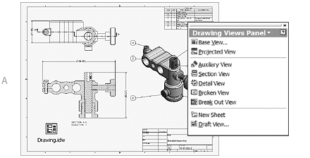
Base View (A)
Let’s start with the base view. Select the Base View tool from the
panel bar. Then select the part or assembly file you want to view,
along with the scale factor and orientation. Selections you make
in the dialog box appear dynamically in the graphics area. Finish
by selecting a point in the graphics area to place your view. Now
you’re ready to create some projected views.
Projected Views
Use the Projected View option to create isometric or orthographic
views. You can place multiple views at one time. The process is
simple: Select Projected View from the panel bar and pick the base
view to work from. The direction you move the mouse controls which
projected view appears. Horizontal or vertical movement generates
orthographic views, and diagonal creates an isometric view. After
placing the various views, right-click and select Create from the
shortcut menu.
Section Views
Section views can be painful to create in AutoCAD but are generated
instantly in Autodesk Inventor. Simply pick Section View from the
panel bar, select the view you want to section, and draw the line
that defines the plane that cuts through the part or assembly. Then
right-click to continue and complete the Section View dialog box.
Complete the command by placing the final view.
Even More Views
Autodesk Inventor supports many different view types, from Detail
views to Broken views. All are easily found in the Drawing Views
panel bar. Note that you don’t need to wait until a part is completed
to create your drawing file. Since the Autodesk Inventor files are
associative, the drawing file always updates to accommodate the
most recent view. Would you like to grab the dimensions you placed
while creating your model? Just right-click in the desired view
and pick Get Model Annotations. To add dimensions, right-click in
the panel bar to switch to the Drawing Annotations panel bar. Here
you’ll find the wonderful General Dimension tool we used in Step
5, along with several other dimensioning tools.
Are you worried about layers, text styles, dimension
styles, and so forth? No worries—you can duplicate all your familiar
AutoCAD settings in the Standards dialog box. There are many drafting
standards available for you to use (ANSI, ISO, JIS, and so on),
or you can create your own. If you aren’t ready to make that jump
to 3D, try creating your 2D drawing in the Autodesk Inventor drawing
file. The added intelligence of the Autodesk Inventor parametric-based
modeler takes you further and faster than AutoCAD. You can still
set up constraints between the views so that if you change the hole
in one view, it updates in the corresponding views. It’s amazing!
Comparing the IDW to working with AutoCAD paper space
layouts doesn’t even begin to do it justice. The IDW is exponentially
more intelligent, eliminating so much of the tedium we face with
paper space layouts. < back next
>
|

