| We have our
constrained and dimensioned 2D sketch, and now we’re ready to make
the leap to 3D part modeling. In Autodesk Inventor lingo that means
you’ll move from Sketch mode to Feature mode. Now you’re ready to
take your base sketch and turn it into your base feature.

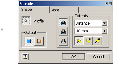
(A) I’d say that
9 times out of 10 you’re going to use the Extrude tool first. This
tool adds depth to your sketched feature. All the Feature tools
have easy-to follow dialog boxes that dynamically change depending
on the input you’ve provided.
There are two types of features in Autodesk Inventor software—sketched
features and placed features. A sketched feature consists of a sketch
drawn on a plane (an existing face or a work plane), transformed
into a 3D feature by extruding, revolving, sweeping, or lofting
it. A placed feature doesn’t require a sketch and can be added directly
to an existing feature. Fillets, chamfers, and holes are examples
of placed features.
In your browser you can find all your features displayed in the
order you created them. You can edit them at any time by simply right-clicking
on the desired feature and selecting Edit Feature from the shortcut
menu. You can even reorder features from the browser.
Taking a Good Look
To survive in 3D you’ll need to learn how to control your viewing
angle. It won’t take you long to realize that you can zoom in and
out of the current display by using the wheel on your mouse. (If
your mouse doesn’t have a wheel—run out right now and get one that
does!) But here’s the glitch—in AutoCAD we’re used to pushing the
wheel forward to zoom in, and pulling the wheel toward us to zoom
out. It’s the exact opposite in Autodesk Inventor, and this will
drive you crazy at first. Think of it like this: as you push the
wheel forward, you’re pushing the object further away, as you pull
the wheel toward you you’re pulling the object closer to you. It’s
an easy adjustment, but it takes a little getting used to. There
are seven different viewing commands on the Standard toolbar. The
first two, Zoom All and Zoom Window,work exactly as they do in AutoCAD. The Zoom tool works the same as the wheel on your mouse—as you move
your cursor up, the part moves farther away, and vice versa. The
fourth tool is Pan (which you are a pro at). This leaves us with
three tools that require just a little more explanation.  Zoom Selected:You pick a face and Autodesk Inventor fills the
screen with the selected face (or faces).
 Rotate: Similar to AutoCAD 3DORBIT, this option dynamically
rotates the part. Pressing the space bar while in this mode displays
the Glass Box as an additional viewing aid.
 Look at:This option changes you to the plan view
of the selected face or edge.
More Display Controls
Two function keys are worth mentioning at this point. F4 can also be used to
dynamically rotate your part. F5 performs the equivalent of a Zoom Previous. If you press F5 too many times and want to step forward again through your
zooms, simply press Shift F5. I use these three options often while designing
in Autodesk Inventor (and I wish AutoCAD had the same function key setup!). Finally, life in Autodesk Inventor would not be complete without the frequently
used Isometric View option. It’s easy to switch to a standard isometric view
by right-clicking and selecting Isometric View. I do this all the time. If you don’t
like the default isometric view, it’s easily changed to a view of your choice.
< back next
>
|

