How three types of IK chain solves are used to set up character motion: Single chain solver, Multi-chain solver and the Spline-chain solver.
Use the single-chain IK solver to set up character motion very quickly and adjust the motion in a highly visual way.
The single-chain IK solver option can be set within the Animation > IK > Add IK Handle options window.
With the single-chain solver, the solution is unique, which means that the behavior of the skeleton is the same whether the animation is played forward or backward, whether a constraint/handle is moved away and back, and so on. Therefore, you can interactively move and play back your skeleton motion, and render, without needing to use Run IK.
With the multi-chain IK solver, skeletons have non-unique behavior; that is, the motion of joints can change unpredictably, depending on whether you play back the animation, do a viewframe, move a constraint, or undo a transformation. The solution to this problem is to do a separate, non-interactive operation to “bake” the skeleton motion using the Run IK tool. (To render a Multi-Chain Solution, you must use Run IK before writing out the SDL file.)
With the single-chain solver, you can put only one handle on each part of a skeleton. For example, you can have one handle for each arm (shoulder to wrist), one handle on each finger (first knuckle to fingertip), and so on. This is very different from the multi-chain IK, in which handles can share joints, and generally overlap considerably.
This figure shows an IK chain with a single-chain IK handle.
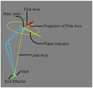
In the default Translation Only setting for the IK Handle, only the Goal and Limb Axis are visible.
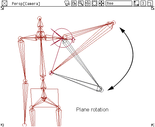
Using the rotation of the IK handle, you can rotate this plane, together with the chain, around the Limb Axis. See the diagram above.
The Pole Axis is shown in the modeling window by a line segment with an “up” arrow at its tip. A projection of this Pole Axis is shown as a dashed line segment drawn to the Plane Indicator’s rotation disc.
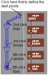
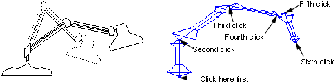
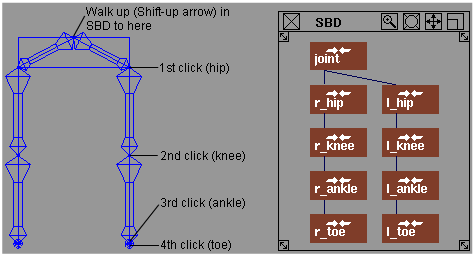
Bone chains are not limited to living creatures. A desk lamp is a simple bone chain. Using a chain of bones, you can easily create a lamp by clicking and forming sections from the base of the lamp to the shade.
 .
.
If you keep clicking now, you’ll keep adding joints to the end of the right toe.
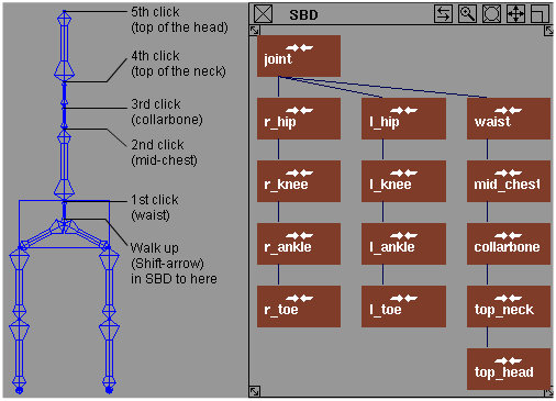
To make the left leg, you want the next joint DAG node you create to be a child of the pelvis node.
 -Up arrow combination to move up the hierarchy until the pelvis is active. You can do this in either the SBD or modeling window.
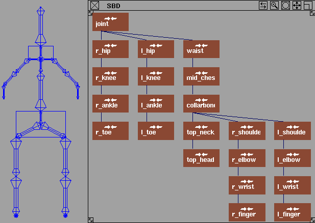
You can also create the left leg by using Edit > Duplicate > Mirror .
.
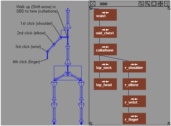
 -Up arrow to move back up the hierarchy to the collarbone, and draw the left arm.
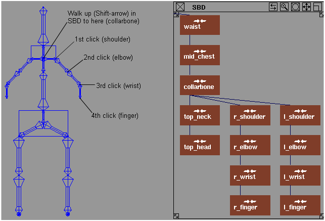
For more information about skeletons, see Animation > Editors > Skeletons .
.
The joints between two aligned bones tend to “lock up” in an IK animation.
If two successive bones in a hierarchy (for example, a thigh and calf bone) are in a straight line, they may not bend even when a constraint on the lowest joint (the ankle) has moved. This occurs because reaching the ankle constraint would need to bend both at the hip and knee, and neither joint wants to move without knowing the other will also move. Otherwise, the ankle would be temporarily too far from its constraint.
To solve this problem for a multi-chain handle, set up joint limits (in the above case, on the knee joint) so that the two limbs can never be in a straight line (2 or 3 degrees from straight should be sufficient). For single-chain, the solution is to set up the rest position so that the joints are not aligned in world space.
How to manipulate skeletons using the multi-handle solver tool.
Choose Animation > IK > Add IK Handle❒ to set the Solver to Multi-handle.
Although the single-chain IK solver is suitable for most inverse kinematics needs, you can also use multi-chain IK handles to manipulate skeletons.
For example, if you need a tail that wags back and forth and bends in opposite directions on each side of the swing, you need a multi-chain solver. With the multi-chain solver, skeletons have a non-unique behavior and you need to bake the skeleton motion using the Run IK tool.
For more information on how it differs from single-chain solver, see Use the single-chain solver.
In some cases, the multi-chain solver can be used to create specialized animations on your skeleton which the single-chain solver may not be able to achieve. For example, if you need a tail that wags back and forth and bends in opposite directions on each side of the swing, you need multi-chain IK handles.
When a multi-chain IK handle is picked, the IK Handle info section in the Information Window has three items not seen with single-chain IK handles:
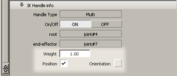
A numerical value that determines the influence of this handle relative to other handles in the skeleton chain.
When checked on, the handle is used to determine the position of the end-effector of the skeleton.
When checked on, the handle is used to determine the orientation of the end-effector’s parent joint.
Position versus Orientation IK handles
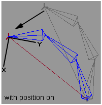
When an IK handle is specified with Position on, moving the IK handle in turn moves the skeleton’s end effector, as with single-chain IK behavior.
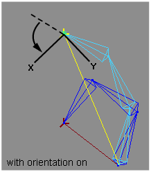
When an IK handle has been specified with Orientation on, rotating the handle affects the rotation of the parent joint of the end effector. As a result, the bone that points to the end effector has the orientation of the IK handle.
See the diagrams in the margin for an illustration of Position on versus Orientation on.
If both Position and Orientation are specified for a multi-chain IK handle, their behaviors are combined. The end effector moves with the IK handle, and the bone pointing to the end-effector is rotated to match the handle’s orientation.
Finding information on the IK handles
For more detailed information on IK handles refer to the section Create a simple spine chain.
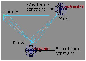
With the multi-chain IK solver, you can overlap IK handles. For example, on an arm, you can place an IK handle from the shoulder to the wrist, and a second handle from the shoulder to the elbow.
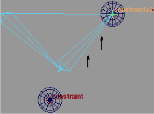
By default, overlapping IK handles will have equal influence on the IK chain.
In the following example, if the shoulder-elbow handle is pulled downward at the same time the shoulder-wrist handle is pulled upward, the arm assumes a position that tries to meet both handles equally:
If you prefer one handle’s influence to be greater than the other’s, you can adjust the handle’s weight in the Information window. In this example, if you want the shoulder-elbow IK handle to have only a small influence, you would set the IK handle weight to a small value (for example, 0.1). As a result, the arm skeleton tends to favor the shoulder-wrist handle, as shown below:
Set the IK handle rotation behavior
How to ’bake’ the IK handles.
When you use the multi-chain solver, you need to do an extra operation to ‘bake’ the IK handle behavior onto the rotations
of the skeleton joints (use Animation > IK > Run IK ). This operation creates keyframe animation directly on the skeleton joints so that the scene can be rendered or the skeleton’s
animation can be further refined by editing the keyframes on the joints.
). This operation creates keyframe animation directly on the skeleton joints so that the scene can be rendered or the skeleton’s
animation can be further refined by editing the keyframes on the joints.
How to control the pieces of the skeleton chain.
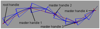
You can use the spline handle to control a piece of skeleton chain. Using the spline handle, the skeleton chain matches a target spline curve. The spline handle makes tail, neck, or snake animation easier. There are four primary purposes of the spline solver:
Bake animation and use Motion Blur compensation
How to apply motion blur to your animation.
There are times when you will want to generate animation curves in place of constraint or expression animation. The Bake plug-in provides the equivalent of Run IK for these cases. Bake creates animation curves for them with keyframes at regularly specified intervals that can be seen and edited by hand.
You can have all the constraints deleted after you’ve baked your animation by choosing the Delete Constraints option on the Bake options window.
If you are going to render an animation with Motion Blur (see Render > Globals for details), you may want to use Motion Blur compensation. The renderer evaluates the animation at a motion blur sample point, interpolating between these values.
Constraint animation is limited to a -180/+180 degree range. If the constraint jumps from -180 to +180, the object doesn’t actually move. But, the motion blur sampling reads a value between those degree ranges, and the object appears to flip, even though it shouldn’t. With the Motion Blur compensation, extra keyframes are created at the motion blur sample times wherever a flipping problem is detected.
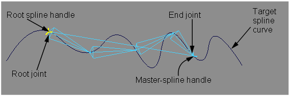
A spline handle is defined on a skeleton chain by a root joint, an end joint, and a target spline curve.
Like single-chain IK handles, spline handles are constraints affecting skeletons. They do not overlap.
When a curve is transformed or animated, the skeleton chain tries to match it. You can also transform or animate the root handle’s position or rotation to change the chain’s position, rolling it along the curve. Rotating the master handle twists each joint on the chain. If you point-constrain the root joint to an object, the start position of the chain is constrained.
There are two kinds of spline handles.
If a master spline handle controls a skeleton chain without a root handle (the root handle may not be created or may have been deleted), the root joint remains fixed, and only the reachable part of the chain follows the spline curve. A tail is a good example; it stays attached to a body, while its end is free to be dragged along a curve. A root handle cannot exist without a master handle.
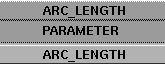
Spline handles can define positions on a curve either by parameters or by arc-lengths. Both types of measurements use relative percentage values.
The following figure shows points on a spline curve defined by parameter distance and by arc-lengths. Each point in this figure is represented by four values: an absolute parameter value, a relative percentage parameter value, an absolute arc-length value and a relative percentage arc-length value.
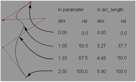
For each spline handle, we can use only relative parameter values and relative arc-length values to define the points or positions.
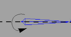
To roll the chain means to rotate the root joint using a lower bone as the rotation axis. Since all lower joints inherit their rotations from upper joints, the rotation on the root joint makes the whole chain roll.
To twist the chain means to rotate each joint (except the end) on the chain using each joint’s lower bone as the rotation axis. If the master handle has its Twist Root attribute set ON, the twist starts from the root joint; otherwise it starts from the second joint.
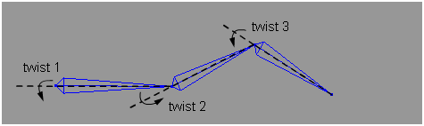
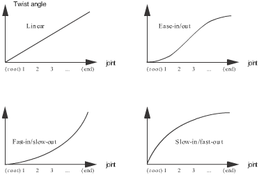
There are four different twist-types that you can use to control the spline handle. (See Twist Type in the Information Window for more information.)
How to find information on the spline handles.
When an IK handle is picked, you can see information about that handle by choosing Windows > Information > Information Window .
.
For information on the other controls, see Create a simple spine chain.
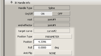
For root handles, the following additional controls appear in the IK handle section of the Information window:
The spline handle’s target curve.
You can change the position by holding down the  (Windows) or
  (Mac) key and the
  , and scrolling in the Position field. You can also type values in the Position field.
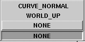
When a spline chain moves along a spiral curve path, it may experience undesirable 180 degree flips or changes of axis. To control this behavior, choose Anti Flip > CURVE_NORMAL or Anti Flip > WORLD_UP. It is set as NONE by default.
If Anti_Flip is set to CURVE_NORMAL or WORLD_UP, you need to set the UP Axis and Front Axis. The two axes must be set to different rotations.
Anti_Flip constrains the root joint’s orientation. The defined Front Axis follows the curve’s tangent. The Up Axis is perpendicular to the Front Axis.
Depending on the orientation of the curve path, you may need to try out an anti-flip setup.
For a master handle, you can change the twist type and the twist angle from the Information window.
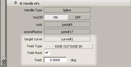
The spline handle’s target curve.
The master spline-handle solution has four types of control which you can specify from this pop-up menu:
Set ON to let the twist start from the root joint. Otherwise, the twist starts from the second joint.
You can set the Twist degree by typing the degree number in this field. You can interactively change the degree value by scrolling using both the
(Windows) or (Mac) key and the .
When Alias is saving out an SDL file, IK and constraint animation is written only for the range of keyframes specified in the Render globals window.