Create any combination and number of point and orientation constraints on an object.
Create a constraint on an object
How to apply a restriction to a DAG node.
The term constraint describes a generalized restriction that can apply to any DAG node. A point constraint modifies the translations of an object to match the position of the object it is constrained to. Orientation and aim constraints modify the rotations of the constrained object so that its local axes match those of the constraint object (orientation), or the selected aim axis points at the constraint object (aim).
Create constraint translates or rotates the object that is being constrained to the position and orientation of the constraint. You can create any combination and number of point and orientation constraints on an object. You can also copy and mirror existing constraints onto a skeleton.
 , or pick an object DAG node in the SBD window.
 from the menu bar.
Depending on the Constraint Type you have set in the Create Constraint Options window. You are prompted to pick either a joint or a node.
For example, the system prompts:
Pick a joint or node to constrain.
You can later change the values of a constraint (but not its type or target) in the Constraint Information section of the Information window (choose Windows > Information > Information Window ).
).
In general it is not useful to apply a constraint directly to a skeleton joint. For example, if a point constraint is applied
to a joint, moving the constrain object would cause the bone to stretch. Normally, you should create IK handles (using Animation > IK > Add IK Handle ) and then constrain the IK handle to an object. To make it easier, if Animation > Tools > Create Constraint is applied to a skeleton joint, an IK handle is created and a null node is added in the SBD window.
 .
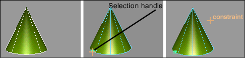
❒ and turn on orientation constraint and create selection handle. Click Go.
.
❒ and turn on orientation constraint and create selection handle. Click Go.
A selection handle is created on the new constraint.
 and click the handle.
 .
.
 .
.
Baking animation and using Motion Blur compensation
There will be times when you will want to generate animation curves from the constraint animation. Bake creates animation curves with keyframes at regularly specified intervals. You can view theses curves and edit them by hand.
Constraint animation is limited to a -180/+180 degree range. If the constraint jumps from -180 to +180, the object doesn’t actually move. However, the motion blur sampling reads a value between those degree ranges, and the object appears to flip. With Bake, extra keyframes are created with the Motion Blur compensation at the motion blur sample times, wherever this flipping problem is detected. The sample points are at the frame, plus/minus the following value:
(RenderByFrame * ShutterAngle) / 720
This means that if you edit the start/end frames in that SDL file, you won’t have the constraint/IK animation outside the original start/end range.
You must re-save the SDL to get any missing constraint/IK animation.
Use Animation > Edit > Constraints On/Off to enable/disable constraint updates instead of visibility.
Constrain one object to another object
Create UV point, orientation or aiming constraints on an object.
Constrain to creates constraints that translates or rotates the constrained objects to the position. You can create any combination and number of UV point, orientation, or aiming constraints on an object.
Constraining an object to another object
, or pick an object DAG node in the SBD window.
 .
.
The system prompts depend on the constraint type that you have set in the Constrain To Options window.
Pick the DAG node whose rotate pivot will be a POINT constraint for the selected node.
Pick the DAG node which the node’s local x axis will AIM at.
Pick the DAG node whose local axis will be an ORIENTATION constraint for the selected node.
 and Animation > Tools > Jack
 .
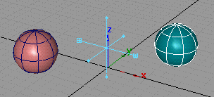
. 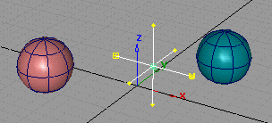 ❒), make sure the Point option is clicked ON.
❒ and pick the sphere at the left.
❒), make sure the Point option is clicked ON.
❒ and pick the sphere at the left.
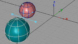
Notice how the jack moves to the sphere that it is constrained to:
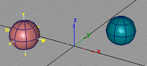
Notice that the jack moves between the two spheres.
The jack is equidistant from the spheres because the weight of the constraints is equal. If the weight of one constraint was
greater, the jack would be closer to the sphere with the greater weighted constraint. To change the weight, use Windows > Information > Information Window.
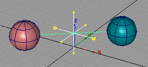
The jack changes color to show it is constrained to the selected sphere:
The jack moves in relation to the two objects it is constrained to:
 and Surfaces > Primitives > Cone.
❒ and make sure Orientation is ON. Click Go then click the sphere.
and Surfaces > Primitives > Cone.
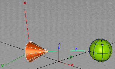
❒ and make sure Orientation is ON. Click Go then click the sphere. 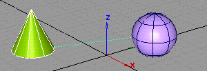 and rotate the sphere.
Notice that the cone rotates along with the sphere.
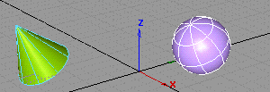
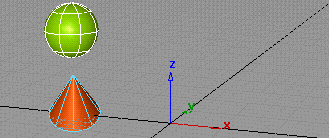
You can see the orientation of an object by turning the local axes of the object on. To do this, choose WindowDisplay > Toggles > Pivots ❒ and in the option box turn the Local Axes Display setting ON.
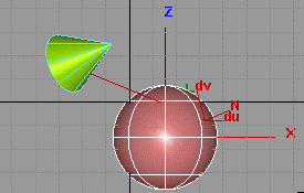
This example illustrates how to make an object always aim toward another object.
and Surfaces > Primitives > Cone.
 to view its local axes.
 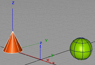 ❒. An option box appears.
Extra controls appear: set the Aim axis to Z and the Up axis to X.
 and move the sphere.
Notice that the cone continues to point at the sphere.

In general, it is not useful to apply a constraint directly to a skeleton joint. For example, if a point constraint is applied to a joint, moving the constraint object stretches the bone.
Normally, you should create IK handles for a skeleton joint (using Animation > IK > Add IK Handle) and then constrain the IK handle to an object. To make this easier, if Animation > Tools > Constrain To is applied to a skeleton joint, an IK handle is created and constrained to the selected object.
 .
.
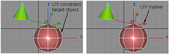
All of the UV constraints related to the picked object will be displayed as markers.
 -select an object. The marker is picked when it turns red.
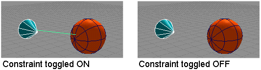
Use Animation > Edit > Constraints On/Off to enable or disable constraints.
When a constraint is OFF, it behaves as if it does not exist.
This function makes it easier to turn on or turn off a group of constraints. For example, you can toggle states of all existing constraints without picking any of them; set constraints of a group of active objects to be the same state; make changes only on the selected types of constraints (say, only change point constraint); or make changes only to the constraints of your picked hierarchies. You can choose to use the constraints either on the constrained side, or the constraining side of the objects.
An individual constraint can be turned ON or OFF from the Information Window when the constrained object is picked.
to set their states (ON or OFF according to the options’ setup.)
Turn constraint display on and off
Use Animation > Show > Constraints to display the constraints on your model while you are working on animation improvements.
To turn constraint display on or off
 or Animation > Tools > Create Constraint.
to turn the display of constraints off. To turn the display back on, select the function again.
or Animation > Tools > Create Constraint.
to turn the display of constraints off. To turn the display back on, select the function again.
Use Delete > Animation > Delete Constraints to remove constraints from your animation.
 , and add one or more constraints to the skeleton’s joint nodes using Animation > Tools > Create Constraint.
to delete the constraints on one of the joint nodes. A confirmation box appears, asking you if you want to delete constraints
on selected DAG nodes.
, and add one or more constraints to the skeleton’s joint nodes using Animation > Tools > Create Constraint.
to delete the constraints on one of the joint nodes. A confirmation box appears, asking you if you want to delete constraints
on selected DAG nodes.


