How to draw a skeleton animation.
Skeletons enable you to create complete character animation sequences before you have to create any of the geometry for the character.
Use Animation > IK > New Skeleton to create the skeleton, then Animation > IK > Add IK Handle
 , Animation > Tools > Create Constraint
 , and Animation > Keyframe > Set Keyframe
 or Animation > Keyframe > Auto Keyframe
 to animate your character in its rotation and translation parameters.
You can create the hierarchical geometry for the character independently from the animation, and you can useAnimation > Editors > Skeletons to turn DAG nodes in this hierarchy into joint DAG nodes. You can then useAnimation > Edit > Overlay Skeleton
 to overlay the animation and other skeleton attributes onto the corresponding joint nodes in the model.
. Animate the skeleton using inverse kinematics (use Animation > IK > Add IK Handle) or any of the standard animation tools.
, or use the Skeleton editor (Animation > Editors > Skeletons) on an existing model that has the same skeleton topology as the first skeleton.
. The system prompts:
Select the root of the skeleton that is to be copied.
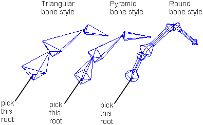
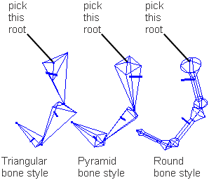
Choose Animation > Tools > Bone Style ❒ to specify bone style.
The following illustrations demonstrate the various bone styles.
Select the root of the skeleton to be copied to.
Pick the root node of the destination skeleton that is to receive the same animation and skeleton attributes as the source skeleton.
After you select the destination skeleton, the translation and rotation animation of each of the joint nodes in the source skeleton are copied to the corresponding joint nodes in the destination skeleton.
See Animation > Editors > Skeletons for a complete description of the joint information.
In addition, the joint limits as well as other joint information is copied to the corresponding joint nodes in the destination skeleton.
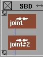
Two skeletons have the same topology if each joint node of Skeleton 1 has the same number of direct descendants joint nodes as Skeleton 2. In the following SBD window diagrams, Skeleton 1 and Skeleton 2 are topologically equivalent.
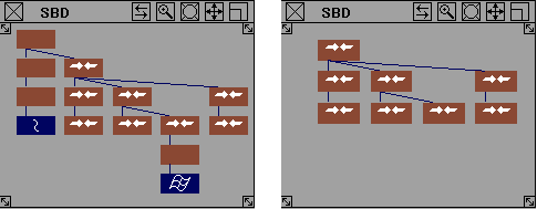
These diagrams show that skeletons with the same topology can have non-joint DAG nodes grouped anywhere above, below, or as siblings to joint nodes. In determining the skeleton from the DAG node hierarchy, the non-joint DAG nodes are ignored.
Sometimes two skeletons can have the same topology, but differ in the significance of their topology. For instance, two skeletons could have two branches of three grouped joint nodes, each branch representing the hip, knee, and ankle joint of a leg. The difference is that in one skeleton, the first branch represents the right leg, and in another, the first branch represents the left leg.
If Overlay skeleton is used to copy animation from one skeleton to the other, the animation of the left leg is copied to the right leg, and vice
versa. To make sure that the animation is copied to the appropriate respective branches, use the SBD swap icon (located in
the SBD window title bar) or an  -arrow (Windows) or
  -arrow (Mac) combination to swap the positions of the branches in the SBD window.
UseAnimation > IK > New Skeleton to create a skeleton that is defined by pivot points or joint positions.
Use Animation > IK > New Skeleton to creates a skeleton.
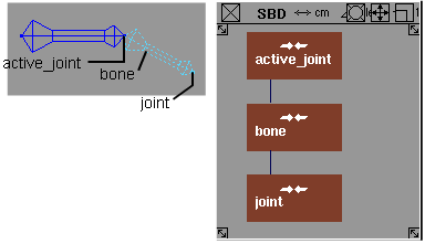
As you create each joint, a DAG node is added to the Scene Block Diagram (SBD) and a bone is drawn in the modeling windows connecting this joint to the previous joint.
Once it is drawn, you can copy and mirror the skeleton using Edit > Duplicate > Mirror , creating an inverse duplicate of the original.

You can also turn existing DAG nodes into joint nodes or make joint nodes into regular DAG nodes, by toggling their joint
state in the skeleton editor (Animation > Editors > Skeletons).
Each time you click in the modeling window when using New skeleton, you create a new joint node that is a child of the active joint node, and a bone is drawn between the two joints.
Each time you create a joint DAG node in this way, the pivot position of the joint DAG node is placed where you last clicked in the window. (You can also create a new joint DAG node by entering the pivot position on the keyboard.)
Bones are drawn between joint nodes and their nearest ancestor joint node by connecting the rotation pivot points of the two
nodes. You can change the shape of the bone (see Animation > Tools > Bone Style ❒) or turn off the display of the bones completely (see Animation > Show > Skeletons ❒).
❒).
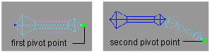
The actual size of a 3D bone is defined by the distance between pivot points. The larger end of the bone shows the location
of the rotation pivot point for the joint DAG node above the bone — the smaller end of the bone points to the rotation pivot
point for the joint DAG node below the bone. Because the bone is defined by the pivot points, you can useTransform > Local > Set Pivot to change the length of a bone.
You can create a chain of joints by clicking several times in an application window. To create a hierarchy , use the  key with one of the four arrow keys on the keypad to move around the joint node hierarchy.
How to display of skeleton bones and their associated constraints or IK handles in application windows on or off.
or the skeleton editor (Animation > Editors > Skeletons). The skeleton is displayed with bone-like geometry.
to turn off the display of these bones. All the skeletons in all the windows are not displayed. To turn the display back
on, select the function again.
Add IK handles to your skeleton
Use inverse kinematics IK handles to control the movement of different parts of your skeleton without disturbing the rest of the skeleton.
Animation > IK > Add IK Handle ❒ is a continuous-action tool in which you add IK handles one at a time to a skeleton. To add single-chain handles, choose
Single-chain in the option box for this tool. Then, select the root joint, and finally the end effector joint. The tool is still active
after this operation, so you can continue to select other parts of the skeleton to put other IK handles on.
❒ or click its icon.
Pick a joint as the root of a single-chain (multi-chain or spline) handle.
Pick a root joint to start the handle. (You can drag a pick box around a joint to select it.)
Pick a descendant joint as the end-effector of the single chain (multi-chain or spline) handle.
Pick an end joint.
Pick a curve node as the target of the spline handle.
Pick the curve.
).
Tips for using the spline handles
You can control the spline handles in the Modeling window in several ways:
If you pick a root handle, either:
 and the
  to move the chain along the curve.
 and the to roll the chain.
If you pick a master handle, use Transform > Rotate and the to twist the chain.
To control the shape of the skeleton
You may want to use spline IK to control the shape of the skeleton, but not its position in space. This is useful if you want one curve to control the shape of a number of similar objects in different locations. To do this:
Creating a neutral pose for IK skeletons
Use Animation > IK > Set Rest Pose to define a neutral pose.
The single-chain IK solver uses a rest pose from which all its unique solutions initiate. The rest pose is a set of values for each joint that provide an initial value for the IK solution.
Each skeleton joint “remembers” a rest value for its translation and rotation, X, Y, and Z values. The rest pose can be copied and mirrored onto a similar skeleton. For information on reverting to a rest pose, see Returning joints and IK skeletons to a rest pose.
To create a neutral pose for an IK skeleton
.
 and the necessary Transform tools.
.
and the necessary Transform tools.
.
Alternatively, you can pick an IK handle to set a rest pose for all joints on the IK chain.
Returning joints and IK skeletons to a rest pose
Using Animation > IK > Assume Rest Pose to return a skeleton to its neutral position.
Each skeleton joint can assume a rest value for its translation, rotation, X, Y, and Z values. You can also return a joint or a regular node back to its neutral pose (that is, having its translation, rotation, X, Y, and Z values set to be zero).
The rest pose and neutral pose are the same by default. The rest pose can be changed by using Animation > IK > Set Rest Pose. For more information, see Creating a neutral pose for IK skeletons.
How to return a skeleton to a neutral or rest pose
.
and Transform tools.
You can also pick an IK handle for all joints on the IK chain to assume a rest pose.
Find information on IK handles
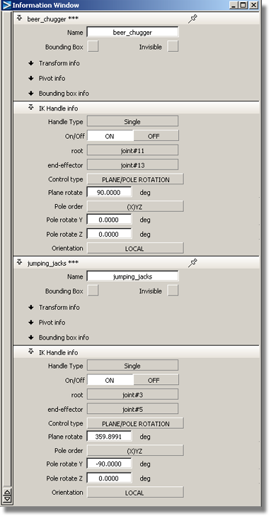
Use the Windows > Information > Information Window menu item to display the details.
To find information on IK handles
 .
. 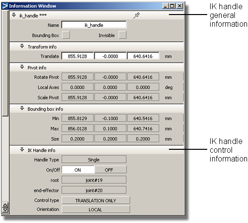
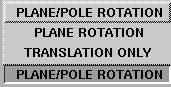
A single-chain IK handle has three levels of control accessed from the Control type pop-up menu.
with the Rotate tool (Transform > Rotate). 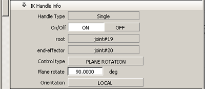
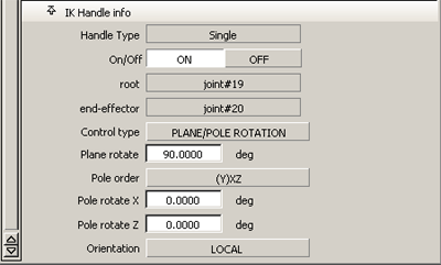
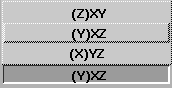
The Pole order field is used to determine which two degrees of freedom are to be used to rotate the Pole Axis. In the earlier example illustrating plane rotation, the skeleton was drawn in the XY plane. Thus the Pole Axis is automatically positioned along the Z-axis (that is, perpendicular to the skeleton plane) when the IK handle is created, and the pole order is ZXY. This means that the Pole Axis is created parallel to the IK handle’s Z-axis (and thus given the blue Z-axis color), and its orientation is adjusted by applying a local X rotation, then a Y rotation, to the Pole Axis.
When to use plane rotation settings for IK handles
If the IK chain never needs to change orientation from its rest position, the default Translation Only setting will be all you need to animate the skeleton. For example, if the legs of a simple biped character in a walk cycle are oriented in a constant direction (that is, the knees always point forward), the IK handles for the legs will only need translation.
However, if that same biped character needs to have a “bow-legged” or “knock-kneed” appearance or if the character is dancing, you might want to rotate the skeleton plane of both legs to achieve this effect. In this case, choose the Plane Rotation setting for those handles in the Information Window, and adjust the Plane Rotate fields accordingly.
Using the plane/pole rotation setting
You will need to adjust the rotation of the Pole Axis, through the “Plane/Pole Rotation” setting, only if the skeleton chain is to be animated through an extremely wide range of motion in the scene. Specifically, if the limb axis of the chain comes near the Pole Axis, an undesirable “flipping” of the chain may occur; generally, you will want to move/animate the Pole Axis so that the handle’s limb axis does not come too close to it during a given scene.
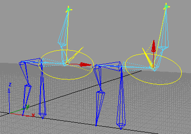
When you create a single-chain IK handle on a chain, a Pole Axis is created perpendicular to the skeleton plane in its rest position. As long as the chain is not contorted very far from this position, and the limb axis of the chain doesn’t approach the Pole Axis, this default position of the Pole Axis is suitable for animating the skeleton. Otherwise, adjusting or animating the Pole Axis may be necessary to avoid flipping in the chain.
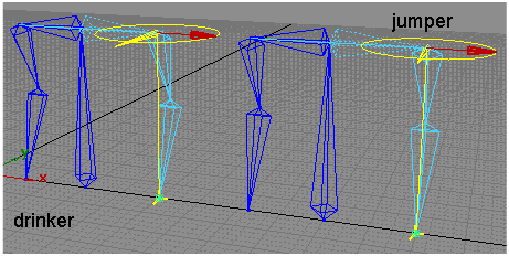
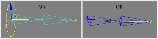
Below is an example of two torsos and how different types of arm movements are achieved through POLE/PLANE ROTATION.
In this example, the two torsos are identical and both have IK handles on the left arms. The default value for Plane rotate is 90 degrees. The default value for Pole rotate Y and Z is zero degrees. The left torso requires a drinking motion, while the right torso will perform a jumping motion.
 to drag the arms up to simulate a drinking motion.
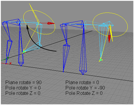
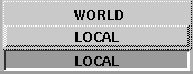
If the root joint of a Single Chain handle inherits a non-proportional scale, Worldspace Orientation for the plane will not work correctly.
Use the motion blur compensation option in Run IK. This will insert additional keyframes at the motion blur sample points near the jumps.
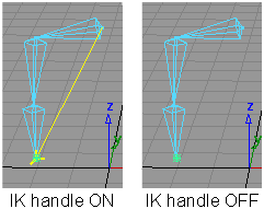
To enable or disable IK handles
Turns on or off IK handles so that they become enabled or disabled.
You can do the following:
When an IK handle is OFF, it behaves as if it does not exist. You can not select it. An individual IK handle can be turned ON or OFF from the Information window.
 to set their states (ON or OFF according to the options' setup.)
Edit > Duplicate > Mirror enables you to create a symmetrical copy of hierarchies according to an axis plane.
This works for skeletons as well as ordinary hierarchies and mirrors IK handles, constraints, rest poses, limits, animation, and selection handles.
With this function, you can do the following:
(By contrast, Layers > Symmetry makes the symmetry by instances, so the geometry is not really duplicated.)
(By contrast, while Layers > Symmetry lets you use an arbitrary plane of symmetry, only the geometry is made symmetric-that is, only the leaf level is affected.
Select Edit > Duplicate > Mirror to open the Mirror Options box. From there, you can select two types of mirroring and three mirroring planes.
Lets you pick a branch as the source branch. The tool duplicates the branch and mirrors its nodes on the new branch.
.
A new branch is created as the sibling of the picked one. The new branch is mirrored across the plane defined in the option box (Mirror Across settings). All IK handles, constraints, animations, and skeletons on the branch are also duplicated and mirrored.
Lets you pick an existing branch as the destination (rather than have the tool create it). Geometries are not mirrored for this option.
.
The first branch is reshaped as a mirror of the second branch. All IK handles, constraints, animations, and skeletons on the first branch are replaced by new objects copied and mirrored according to the second branch.
Mirror provides three mirroring planes under world space. This option specifies the plane to use for later mirror operations.
to open the Mirror Options box.
Run IK to render your animation
Animation > IK > Run IK creates an animation using multi-chain IK handles attached to a skeleton so that the animation may be rendered.
.
to attach IK handles to various joints of the skeleton.
 .
.
You can view the skeleton animation through all the frames of the constraint animation. At the end of this operation, the skeleton is animated using its IK handles.


 to turn the IK Handle display on or off.