Learn how to use the Skeleton editor to set joint information, such as limits, rest position, and stiffness, allowing you to affect how a skeleton moves under inverse kinematics.
Editing skeletons with the skeleton editor
 .
.
 to open the Skeleton Editor window.
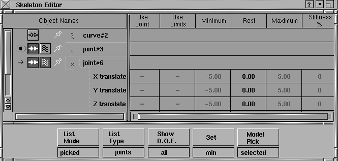
Use the Skeleton Editor to create and modify joint DAG nodes and skeleton hierarchies, and to tailor joint limits, and other properties of an IK chain.
The Skeleton Editor has two sections. On its left side is a lister containing the names of DAG nodes; on the right is a spreadsheet listing the properties of each joint.
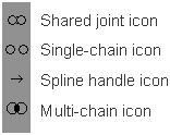
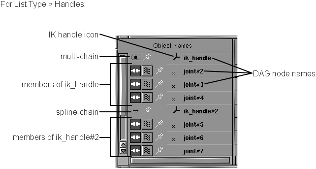
The contents of the lister depend on the selection made in List Mode. Each element in the list has up to four icons, plus a DAG node icon and DAG node name.
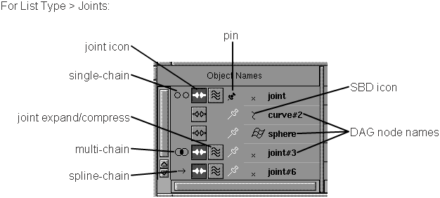

This toggle changes an existing DAG node to a joint node, or changes an existing joint node to a DAG node. If on, it is dark gray with a white bone joint, which indicates that the DAG node is a joint node. In the SBD window the DAG node has a joint icon drawn in its SBD box. If off, it is light gray instead of dark gray, indicating that the DAG node is not a joint node.

With joint DAG nodes, certain joint properties can be tailored for use with IK handles. These properties are listed on the right side of the Skeleton Editor, in the spreadsheet section.
Click this icon to expand the joint to see the joint components that are used and their joint limits. The expansion state is kept so that the joint is expanded the next time you list it. Click the icon again to collapse the joint.
The right side of the Skeleton Editor is a spreadsheet of values that you can edit for different joint node components. (You can edit values only for joints. Before you can edit other objects in this window, you must change them to joints.)
Select the joint expansion icon for one of the joint nodes to see the values for these joints in the spreadsheet. The values for each of the joints in the spreadsheet are used by single-chain or multi-chain IK handles.
This screen shows the Skeleton Editor with the Show D.O.F. menu set to All.
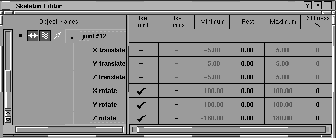
Select Use Joint and Use Limits column entries in the spreadsheet to set them ON (shown by a check mark) or OFF (shown by a dash).
If set to OFF, the parameter does not change during a transformation. This is useful for restricting the motion of a joint. For example, in a skeleton hierarchy of a leg, you may restrict the knee joint so that it can only bend along the x-axis. Therefore, the Y and Z rotations for Use Joint should be OFF.
If set to ON, the joint uses the limits defined in the next two columns, Minimum and Maximum, during transformations. This is useful if you want a joint component to move within a specified joint range. For example, a joint node representing an elbow may have a desired range of 0 to 170 degrees. If Use Limits is ON, and these range limits are set, the elbow joint does not take a value outside that range during a transformation.
If set to OFF, any joint limits set for that joint are ignored. To show this, the Minimum and Maximum cells are grayed out and non-editable.
To define limits, see the description of the Set Button in the Set menu section.
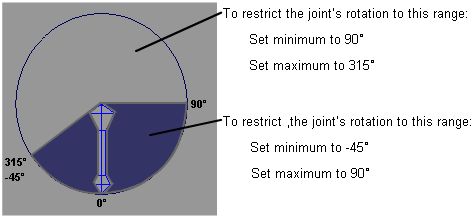
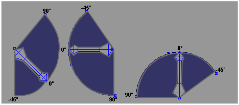
0 degrees is determined with respect to the direction in which you drew the bone originally. If you drew the bone at a slant, the minimum and maximum ranges in the previous example would appear as shown in the following.
These two columns can take any values. The values represent the minimum and maximum values for a joint parameter. For rotation parameters, the values are angles in degrees. For translation parameters, the values are in centimeters. Click in the column on the row of the joint you want to change, and set the minimum or maximum joint value.
Restrictions are that the minimum value must be less than the maximum value, and the rest position must be between the minimum and maximum values. If you enter a minimum value that is greater than the maximum, or if you enter a maximum value that is less than the minimum, the minimum and maximum values are exchanged. If Use Limits is on, these minimum and maximum values restrict the range that a joint parameter can assume.
This column contains values between 0 and 100, which represent the percentage stiffness for each joint parameter. When dragging a chain with a multi-chain handle, there are usually many possible solutions for the chain to reach its goal. Applying stiffness to some joints provides greater control over how the chain reaches its goal.
For example, if you are animating an arm reaching for an object, making the shoulder joint really stiff makes the arm bend at the elbow to reach the object. However, making the elbow joint really stiff keeps the arm straight, and forces the whole arm to reach for the object.
A value of 0% means that there is no stiffness applied to that joint, and it will move as quickly as it can to help the chain’s effector reach its goal. A stiffness of 100% constrains the joint completely, and produces the same effect as not using the joint at all (that is, as if Use Joint is OFF).
The List Mode menu controls which DAG nodes are shown in the lister section of the Skeleton Editor.
The lister shows only the picked DAG nodes, regardless of whether or not they are joint nodes.
The lister shows the currently picked joint node, and every joint node that is an ancestor of that node, up to and including the first joint node. If there are no DAG nodes picked that are joint nodes, nothing is listed.
The lister contains every joint node in the skeleton to which the picked joint nodes belong. Unlike hierarchy, skeleton only lists joint nodes.
If no joint DAG nodes are picked, nothing is listed. If two joint DAG nodes are picked that belong to the same skeleton, the skeleton is only listed once.
The lister shows the picked DAG nodes, and every DAG node above the picked DAG nodes, regardless of whether or not they are joint DAG nodes.
The lister shows the picked DAG nodes, and every DAG node below the picked DAG nodes, regardless of whether or not they are joint DAG nodes.
The lister shows every DAG node in the hierarchy in which the picked DAG nodes are contained.
The lister shows roots of all existing skeletons, whether they are picked or not.
The lister shows all existing skeletons, whether they are picked or not.
Any DAG node in the lister can then be interactively toggled to a joint by clicking on the joint button in the lister. To determine which DAG nodes appear in the lister, the system finds the root DAG node of the picked DAG node, and lists every DAG node below that root DAG node.
Example of Hierarchy, Below, and Above
The Hierarchy, Below, and Above modes are useful if you have already created a hierarchical model and want to use inverse kinematics to move or animate it. Any DAG node in the lister can then be interactively toggled to a joint by clicking on the joint button in the lister.
These modes can also be used to limit the information in a hierarchical list to parts of the skeleton you are working on.
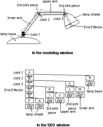
The following example shows a desk lamp and its skeletal hierarchy:
The Show D.O.F. pop-up menu controls the rotation and translation parameters displayed when you click the joint expansion button for a joint node. The D.O.F. stands for degrees of freedom viewed from the point of IK control.
This is the default mode. When you click a joint node’s joint expansion icon in the Skeleton Editor lister, you see all possible degrees of freedom for that joint node (that is, X, Y, and Z rotations and translations).
When you click the joint expansion button of a joint node, only the degrees of freedom that have the Use Joint column ON appear in the lister.
The Set menu lets you set the Minimum and Maximum columns in the currently selected rows to the current values of the corresponding joint parameters.
Choose joints in the Skeleton Editor lister, and then choose one of these settings from the Set menu:
The current minimum parameter value for all selected rows will be set to the current value of the joint’s corresponding parameter.
The current maximum parameter value for all selected rows will be set to the current value of the joint’s corresponding parameter.
For example, suppose a joint’s Y Rotation value is set to 60 degrees:
The DAG nodes that you select in the Skeleton Editor are automatically picked in the modeling world. After this operation is complete, the selected and unselected items in the Skeleton Editor lister correspond exactly to the picked and non-picked DAG nodes in the modeling world.
This operation is used most successfully when the List Mode is skeleton or hierarchy. This is because the contents of the list in the Skeleton Editor do not change after the Model Pick > Selected operation.
Sometimes it is not possible to pick all DAG nodes that are selected in the Skeleton Editor. This is because the Skeleton Editor is designed to display hierarchies of DAG nodes. These hierarchies can be selected in the Skeleton Editor lister window. However, DAG nodes that are ancestors or descendants of each other cannot be picked at the same time in the modeling world (this is known as a pick conflict).
To resolve this pick conflict, if ancestor and descendant DAG nodes are selected in the Skeleton Editor lister, the lowest descendant DAG nodes that are selected are picked in the modeling world. The DAG nodes that could not be picked in the modeling world are deselected in the Skeleton Editor lister.
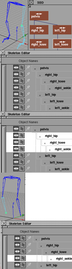
An example best demonstrates how this works. Suppose you have created a two-legged figure:
Since the left knee is not selected in the lister, it is unpicked in the modeling world. Since there is a pick conflict between the joints in the right leg, the lowest joint is selected (right_ankle), and is picked in the modeling world. The other joints in the right leg are unselected in the lister, since they could not be picked in the modeling world.
The Skeleton Editor is a spreadsheet that lets you edit several selected elements from a column at once. You can use the lister section of the Skeleton Editor to select one or more elements from the list. Simply click the first element to select, and drag your cursor up or down to the last element of the list to be selected. The selected items are highlighted.
You can hold down the  key while selecting to add or remove elements of a selected list. For example, to select the second, third, seventh, eighth,
and ninth elements of the list, click the second element and drag to the third element. Then hold , click the seventh element and drag to the ninth element. Now all five elements are selected.
key while selecting to add or remove elements of a selected list. For example, to select the second, third, seventh, eighth,
and ninth elements of the list, click the second element and drag to the third element. Then hold , click the seventh element and drag to the ninth element. Now all five elements are selected.
Once you have selected more than one item on the list, you can globally edit all the selected items. Global editing works both in the lister and spreadsheet sections. For example, if you have five elements that you want to be joint nodes, select the five elements and click the joint icon for any one of the five elements. All five elements are now joints. List the joints for one joint DAG node by clicking on the joint expansion button, and select all the joint properties. Click under the Use Limits column of one of the selected rows, and all the joints now have the same Use Limits value (ON or OFF).
Caution! Clicking several selected elements to toggle the joint icon off also deletes all the associated joint information, such as joint limits and joint stiffness, and all joint constraints, or IK handles attached on the joints.