The Render Globals window contains the global rendering parameters which control how the overall scene will render.
The global rendering parameters control how the overall scene will render.
Determines if several frames of an animation are rendered (ON), or only the current (single) frame is rendered (OFF). The Animation setting determines if animation is included in the SDL file. If Animation is ON, the Animation Range From parameter and the Animation Output Filename Extensions parameters become available. The default setting is OFF.
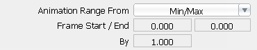
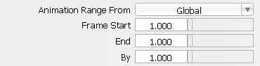
Determines which frames of an animation are rendered when Animation is ON. The default setting is TIME SLIDER.
Animation Output Filename Extensions
The Animation Output Filename Extensions parameters control the format of the rendered images’ file name extensions. These parameters are only available if Animation is ON.
The total number of characters in file name extensions. If the number of digits in the frame number is less than the Frame Padding value, then leading zeros are added to the extension. For example, if the frame number is 12, and the Extension padding value is 4, the image file will have the extension <pixfile>.0012. The valid range is 0 to infinity. The slider range is 1 to 10. The default value is 1.
Global Quality Parameters (Low, Medium, High)
The Global Quality Parameters control how surfaces are tessellated during rendering. Default values are different depending on the Global Quality Level setting. The default values listed below are for the MEDIUM Global Quality Level.
The maximum allowable distance (measured in centimeters) between a NURBS surface and its tessellated version. The Mesh Tolerance value controls how smoothly surfaces are tessellated. The lower the Mesh Tolerance value, the smoother the appearance of surfaces; however, rendering times may also increase. If the silhouettes of surfaces appear faceted or jagged, decrease the Mesh Tolerance value. The slider range is 0.001 cm to 0.10 cm. The default value is 0.05 cm for Medium quality.
If the V9 Tessellator option is selected, determines which set of render quality parameters are used during rendering. Render quality parameters control subdivision, anti-aliasing, and raytracing limits. The default setting is PER OBJECT.
| Per object | each object renders based on its Object Rendering Parameters |
| Global | all objects render based on the Global Quality Parameters (see Global Quality Parameters (Low, Medium, High)) |
The method used to subdivide surfaces during rendering. The default value is Adaptive.
| Adaptive | Subdivides surfaces (patches) into triangles based on surface curvature. (Faces cannot be adaptively subdivided.) Surfaces with high curvature are divided into more triangles than flatter surfaces with low curvature. If Subdivision Type is Adaptive, then the Adaptive Minimum, Adaptive Maximum, and Curve Threshold parameters become available. |
| Uniform | Subdivides surfaces into uniformly sized triangles (that is, without taking surface curvature into account). Trimmed surfaces must be adaptively subdivided. Only the U Divisions value is used for subdividing faces. When Subdivision Type is Uniform, the U Divisions and V Divisions parameters become available. |
The minimum and maximum number of subdivisions between CVs in both U and V directions. Values must be powers of 2 between 0 and 7 (either 1, 2, 4, 8, 16, 32, 64, or 128). If you enter any other value between 1 and 256, the next highest valid value is used. The default value is 2 for Adaptive Minimum and 4 for Adaptive Maximum.
The Anti-aliasing Levels control the quality of anti-aliasing used during rendering. The default values listed are for the Medium Global Quality Level.
If you are rendering a scene with a few small details that can easily be missed, try setting the Minimum value to 0 or 1, the Maximum value from 4 to 8, and the Threshold value from 0.9 to 1.0. This gives very short rendering times and excellent image quality.
Uses the colors at each corner of a pixel to determine if finer anti-aliasing is required. If the value differences at each pixel corner are greater than the Threshold value, the pixel is subdivided again. The valid/slider range is 0 to 1 (the maximum number of samples is always taken). The default value is 0.7.
The Raytracing Maximum Limits set limits on the number of reflections, refractions, and shadows possible during raytracing. The default values listed are for the Medium Global Quality Level.
The maximum number of times that a camera ray can be reflected. The Maximum Reflections value overrides (that is, limits) all shaders’ Reflect Limit values (see Reflect Limit). The valid range is 0 to infinity. The slider range is 0 to 10. The default value is 4.
The maximum number of times that a camera ray can be refracted. The Maximum Refractions value overrides (that is, limits) all shaders’ Refract Limit values (see Refract Limit). The valid range is 0 to infinity. The slider range is 0 to 10. The default value is 4.
The maximum number of times any surface can be reflected or refracted and still receive shadows (in the reflection/refraction). The Max Shadows Levels value overrides (that is, limits) all shaders’ Shadow Limit values (see Shadow Limit). The valid range is 0 to infinity. The slider range is 0 to 10. The default value is 4.
The Render Globals window contains the Object Rendering Parameters, which control how individual objects will render.
The Composite Rendering Options control whether objects are anti-aliased against the background. Composite rendering is used for image compositing and games design.
Renders objects so that they are not anti-aliased against the background. For example, a pixel on the edge of an object is not mixed with the background color—only the subsamples actually striking the object are used to compute the color of the pixel. The default setting is OFF.
In TIFF terms, Composite Rendering generates unassociated alpha. The RGB anti-aliased images that result won’t look too anti-aliased due to the unassociated alpha.
The number of subsamples required for the pixel as a whole to be considered part of the object and not part of the background. For example, if the Coverage Threshold value is 0.5, then at least half of the subsamples must strike the object or it will be considered as a missed ray, determined by the mask generated by the renderer. This lets you control the bleed around the edges of a sprite. This parameter is available only if Composite Rendering is ON. The valid/slider range is 0 to 1. The default value is 0.5.
Controls how bounding boxes are stored in memory. The default setting is Full.
| Full | the bounding box of each triangle is kept in memory to speed up raytracing |
| Partial | the bounding box is encoded, saving memory, but sacrificing a small amount of speed |
| None | no bounding box is stored, saving even more memory, but at a significant loss of speed |
Reducing memory usage usually increases rendering time. However, if the raytracer starts to swap, reducing memory usage actually improves performance. See Optimization
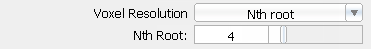
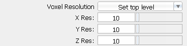
Controls how voxel resolution is determined. Changing voxel resolutions affects the amount of memory needed. Only experienced users should adjust the Nth root, X Res, Y Res, or Z Res values. The default setting is Nth root.
Texture Caching Memory Options
The Texture Caching Memory Options control how File textures are stored in memory. Alias does not read every component of every texture file into memory. The MIPMAPs are tiled, and only the portions for the area that the renderer is working on are kept in memory.
You can specify a cache size that maintains only what has to be in memory at any time, and load and unload texture tiles (parts of a texture) as need. This can dramatically reduce the amount of memory used.
Controls how File textures are stored in memory. The default setting is Off.
| Off | all File textures are kept in memory at all times |
| On | Creates a cache of texture tiles (parts of a texture), which is kept on disk, retrieved as needed, and deleted from memory as other tiles are needed. |
| Per texture | Creates a cache of texture tiles only for File textures which have CacheON (see Cache). All File textures which have CacheOFF are kept in memory at all times. |
You use the Blur Effects parameters to do post-rendering anti-aliasing and motion blur during animations.
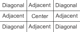
Does more anti-aliasing after rendering is complete, using a 3 pixel by 3 pixel Bartlet filter for each pixel. This produces softer edges and improved image quality. If Post Filter is ON, the Post Center, Post Adjacent, and Post Diagonal parameters become available. The default setting is OFF.
A Bartlet filter blurs each pixel in an image using a 3 pixel by 3 pixel sample. The filter applies a weight to the color of the center pixel, the adjacent pixels, and the diagonal pixels. The ratio between the weighted center pixel color and the weighted surrounding pixel colors determines how much the center pixel’s color is blended with the surrounding pixel colors.
Blurs the motion of objects to produce smoother animations. Motion blur is only calculated for objects which have Motion Blurred on (see Motion Blurred) and for cameras which have Motion BlurON (see Motion Blurred). By default, all objects have Motion Blurred turned on, and all cameras have Motion Blur turned off. If Motion Blur is OFF, motion blur is not calculated regardless of individual object settings. If Motion Blur is ON, the Shutter Angle parameter becomes available. The default setting is OFF.
The angle (in degrees) that the camera shutter remains open. The greater the angle, the greater the motion blur effect. For example, if the Shutter Angle value is 180, moving objects are blurred over half of the frame step time. The Shutter Angle parameter is only available when Motion Blur is ON. The valid/slider range is 1 to 360. The default value is 144.
Controls whether transparent objects appear in the camera’s depth file (see Depth). If No Transp. in Depth is OFF, transparent objects appear in the depth file. If No Transp. in Depth is ON, the Transparency % parameter becomes available. The default setting is OFF.
The level of transparency an object needs in order to appear in the camera’s depth file (see Depth). For example, if the Transparency % value is 0.8, objects that are more than 80 percent transparent do not appear in the depth file. This parameter is only available if No Transp. in Depth is ON. The valid/slider range is 0 to 1. The default value is 1.
Saves spot light shadow depth maps to disk for spot light’s that have Use Depth MapON (see Use Depth Map). The default setting is OFF.
Keeps spot light shadow depth maps in memory for spot light’s that have Use Depth MapON (see Use Depth Map). The default setting is OFF.
Depth Maps in Memory acts the same as the -k option for the command line renderer.
This is relevant only for the raytracer/powertracer.
The camera depth file is output and saved in this file format (see Depth). The default setting is ALIAS.
| Alias | Alias camera depth file format (see Alias Camera Depth File Format in the File Formats online documentation) |
| Composer | Composer depth file format |
Controls whether rendering produces frames or fields. A frame consists of two fields, odd and even. The odd field contains every second line starting at the first line. The even field contains every second line starting at the second line. The default setting is OFF.
| Off | frames |
| Both | both odd and even fields |
| Odd | odd fields only |
| Even | even fields only |
If Fields is either Both, Odd, or Even, an additional parameter becomes available.
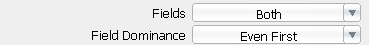
This parameter defines the order that the fields are rendered. The default setting is ODD FIRST.
| Odd First | odd fields first |
| Even First | even fields first |
You can use field-rendered Pix Backdrops when rendering Fields. If you render fields, the renderer uses pixbackdrop.*e during the even field rendering and pixbackdrop.*o during the odd field rendering. The field-rendered Pix Backdrop files is used only if the frame-rendered files (pixbackdrop.1, pixbackdrop.2, and so on) do not exist. See Backdrop.
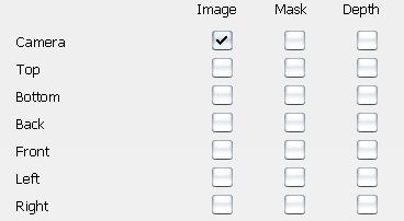
Determines whether a camera produces an image file, a mask file, or a depth file, or all three. You can select one camera only.
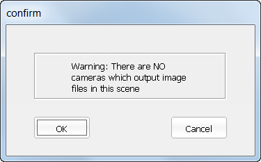
If all camera toggles are OFF when you do a render (Render > Render ) or save an SDL file (File > Export > SDL
 ), the following confirm box is displayed.
The renderer produces an RGB image (see Format). The default setting is ON for the perspective camera, and OFF (no image produced) for the orthographic cameras.
The renderer produces an 8-bit mask or matte file for use with compositing or paint software. If Mask is ON and the image file output Format is TIFF, TIFF16, RLA, or SGI, the renderer produces not a separate mask file but a four-channel Image file (RGBA). The fourth channel (A) represents the mask information. The default setting is OFF (no mask file produced) for all cameras.
The renderer produces a camera depth file (see Depth Format). The default setting is OFF for all cameras.
The X and Y resolution of the rendered image. The valid range is 0 to infinity. The slider range is 0 to 2048. The default setting is 645 for X Resolution and 486 for Y Resolution.
If Image XY Ratio Lock is ON, then you cannot set the X Resolution and Y Resolution values independently. You can also set image resolution using several predefined values (see Predefined Resolutions).
The ratio of each individual pixel’s width to its height for a display or recording device. Most devices, including the monitor screen, use square pixels, so the pixel aspect ratio is 1/1 = 1. Some devices, however, use non-square pixels.
If you are rendering an animation that you plan to display on or record to one of these devices, you must set the Pixel Aspect Ratio value to the device’s pixel aspect ratio value. The rendered animation will then look squashed or stretched when you view it on the monitor screen, but will have the proper proportions when you view it from the device. You can also set the Pixel Aspect Ratio by selecting a predefined value (see Predefined Resolutions). The valid range is 0 to infinity. The slider range is 0 to 1. The default value is 1.
| Device | Pixel Aspect Ratio |
|---|---|
| IRIS NTSC | 1.0 |
| IRIS PAL | 1.0 |
| Raster Tek's Hidef Frame Buffer | 1.0 |
| Abekas Internal Frame Buffer | 1.33 |
| Raster Tek's NTSC Frame Buffer | 1.125 |
| Quantel's Harry Interface | 1.33 |
| Full Frame 1K width | 1.11 |
| Motion Picture 1K with sound track | 1.0 |
| Motion Picture, no sound track | 1.0 |
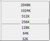
The Predefined Resolutions section of the Render Globals window contains a list of common screen resolutions. You can select a predefined resolution by clicking on it. The corresponding Image File Output parameters (X Resolution, Y Resolution, and Pixel Aspect Ratio) are automatically set.
You can change the X Resolution, Y Resolution, or Pixel Aspect Ratio values of a predefined resolution by double-clicking in the appropriate field in the Predefined Resolutions list, and entering a new value. You can also add a predefined resolution to the list by clicking the Add button, or delete a predefined resolution from the list by selecting the predefined resolution and then clicking the Delete button.
If you change a predefined resolution, the change is automatically written to your misc_data directory in a file called resolutions. The predefined file is located within the active project. If no file exists, the system creates the Alias default.
Hidden Line Rendering Parameters
The Hidden Line Rendering Parameters control the appearance of surfaces during hidden line rendering.
Determines which set of Hidden Line Rendering Parameters are used during hidden line rendering. The default setting is PER OBJECT.
| PER OBJECT | each object renders based on its shader’s Hidden Line Rendering Parameters |
| GLOBAL | all objects render based on the Hidden Line Rendering Parameters in the Render > Globals window window
|