Splines include the following object types: Line, Rectangle, Circle, Ellipse, Arc, Donut. NGon, Star, Text, HelixSection. Extended Splines include the following object types: WRectangle. Channel. Angle. Tee, and Wide This topic covers general aspects of spline and extended spline creation, including the parameters available on rollouts common to all spline objects.
For parameters unique to a particular spline or extended spline type, see its section.
To combine shapes while creating them:
 Create panel, turn off the check box next to the Start New Shape button.
Each spline is added to the compound shape. You can tell you are creating a compound shape because all the splines remain selected.
Issues to remember about creating shapes:
To create a spline using keyboard entry:
Object Type rollout (Splines and Extended Splines)
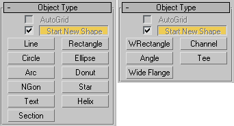
Lets you automatically create objects on the surface of other objects by generating and activating a temporary construction plane based on normals of the face that you click.
For more information, see AutoGrid.
A shape can contain a single spline or it can be a compound shape containing multiple splines. You control how many splines are in a shape using the Start New Shape button and check box on the Object Type rollout. The check box next to the Start New Shape button determines when new shapes are created. When the box is on, 3ds Max creates a new shape object for every spline you create. When the box is off, splines are added to the current shape until you click the Start New Shape button.
Lets you name an object and assign it a viewport color. For details, see Object Name and Wireframe Color.
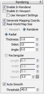
Lets you toggle shape renderability in the viewports and rendered output, specify cross-section settings, and apply mapping coordinates.
You can animate render parameters, such as the number of sides, but you cannot animate the Viewport settings.
You can convert the displayed mesh into a mesh object by applying an Edit Mesh or Edit Poly modifier or converting to an editable mesh or editable poly object. If Enable In Viewport is off when converting, closed shapes will be “filled in” and open shapes will contain only vertices; no edges or faces. If Enable In Viewport is on when converting, the system will use the Viewport settings for this mesh conversion. This gives maximum flexibility, and will always give the conversion of the mesh displayed in the viewports.
Turn this on to apply mapping coordinates. Default=off.
3ds Max generates the mapping coordinates in the U and V dimensions. The U coordinate wraps once around the spline; the V coordinate is mapped once along its length. Tiling is achieved using the Tiling parameters in the applied material. For more information, see Mapping Coordinates.
Controls the scaling method used for texture mapped materials that are applied to the object. The scaling values are controlled by the Use Real-World Scale settings found in the applied material's Coordinates rollout. Default=off.
The ratio of width to length. Adjusting Aspect automatically changes the Length setting to establish the indicated aspect ratio with respect to the Width value.
When Lock is on, the Aspect setting is unavailable and adjusting Width or Length automatically changes the other to maintain the aspect ratio.
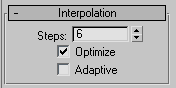
These settings control how a spline is generated. All spline curves are divided into small straight lines that approximate the true curve. The number of divisions between each vertex on the spline are called steps. The higher the number of steps, the smoother the curve.
Spline steps can be either adaptive (that is, set automatically by turning on Adaptive) or specified manually.
When Adaptive is off, use the Steps setting to specify the number of divisions between each vertex. Splines with tight curves require many steps to look smooth while gentle curves require fewer steps. Range=0 to 100.
When off, enables manual interpolation control using Optimize and Steps. Default=off.
When on, Adaptive sets the number of steps for each spline to produce a smooth curve. Straight segments always receive 0 steps.
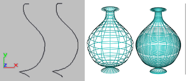
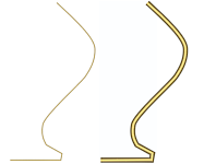
Optimized spline left and adaptive spline right. Resulting wireframe view of each, respectively, on the right.
The main use for manual interpolation of splines is in morphing or other operations where you must have exact control over the number of vertices created.
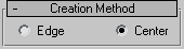
Many spline tools use the Creation Method setting. Here you choose to define splines by either their center point or their diagonal.
Text and Star do not have a Creation Method rollout.
Line and Arc have unique Creation Methods rollouts that are discussed in their respective topics.
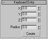
You can create most splines using keyboard entry. The process is generally the same for all splines and the parameters are found on the Keyboard Entry rollout. Keyboard entry varies primarily in the number of optional parameters. The image above shows a sample Keyboard Entry rollout for the Circle shape.
The Keyboard Entry rollout contains three fields for the X, Y, and Z coordinates of the initial creation point, plus a variable number of parameters to complete the spline. Enter values in each field and click the Create button to create the spline.
Use Line to create a free-form spline made of multiple segments.
Use Rectangle to create square and rectangular splines.
Use Circle to create closed circular splines made of four vertices.
Use Ellipse to create elliptical and circular splines.
Use Arc to create open and closed circular arcs made of four vertices.
Use Donut to create closed shapes from two concentric circles. Each circle is made of four vertices.
Use NGon to create closed flat-sided or circular splines with any number (N) of sides or vertices.
Use Star to create closed star-shaped splines with any number of points. Star splines use two radiuses to set the distance between the outer points and inner valleys.
Use Text to create splines in the shape of text.
Use Helix to create open flat or 3D helices or spirals.
Section is a special type of spline that generates shapes based on a cross-sectional slice through mesh objects.


 (Shapes)