Command entry:
Create panel


(Shapes)
Splines
Object Type rollout
Section
Command entry:Create menu
Shapes
Section
Section is a special type of spline that generates shapes based on a cross-sectional slice through mesh objects.
The Section object appears as a bisected rectangle. You simply move and rotate it to slice through one or more mesh objects,
and then click the Create Shape button to generate a shape based on the 2D intersection.
Procedures
To create and use a section shape:
- Create or open a scene containing one or more mesh objects.
- On the Create panel, click (Shapes).
- On the Object Type rollout, click Section.
- Drag a rectangle in the viewport in which you want to orient the plane. For example, to place the Section object parallel
to the XY home grid, create the spline in the Top viewport.
The Section object appears as a simple rectangle with crossed lines indicating its center. With the default settings, the
rectangle is for display purposes only, because the effect of the Section object extends throughout its plane to the full
extents of the scene.
- Move and rotate the section so that its plane intersects mesh objects in the scene.
Yellow lines are displayed where the sectional plane intersects objects.
- On the Section Parameters rollout on the command panel, click Create Shape, enter a name in the resulting dialog, and click
OK.
An editable spline is created, based on the displayed cross sections.
Interface
Rendering and Interpolation rollouts
All spline-based shapes share these parameters. See Splines for an explanation of these parameters.
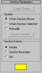
Section Parameters rollout
- Create Shape
-
Creates a shape based on the currently displayed intersection lines. A dialog is displayed in which you can name the new object.
The resulting shape is an editable spline consisting of curve segments and corner vertices, based on all intersected meshes
in the scene.
Update group
Provides options for specifying when the intersection line is updated.
- When Section Moves
-
Updates the intersection line when you move or resize the Section shape.
- When Section Selected
-
Updates the intersection line when you select the section shape, but not while you move it. Click the Update Section button
to update the intersection.
- Manually
-
Updates the intersection line only when you click the Update Section button.
- Update Section
-
Updates the intersection to match the current placement of the Section object when using When Section Selected or Manually
option.
NoteWhen using When Section Selected or Manually, you can offset the generated cross section from the position of the intersected
geometry. As you move the section object, the yellow cross-section lines move with it, leaving the geometry behind. When you
click Create Shape, the new shape is generated at the displayed cross-section lines in the offset position.
Section Extents group
Choose one of these options to specify the extents of the cross-section generated by the section object.
- Infinite
-
The section plane is infinite in all directions, resulting in a cross section at any mesh geometry in its plane.
- Section Boundary
-
The cross-section is generated only in objects that are within or touched by the boundary of the section shape.
- Off
-
No cross section is displayed or generated. The Create Shape button is disabled.
- Color swatch
-
Click this to set the display color of the intersection.
Section Size rollout
Provides spinners that let you adjust the length and width of the displayed section rectangle.
- Length/Width
-
Adjust the length and width of the displayed section rectangle.
NoteIf you convert the section grid to an editable spline, it's converted to a shape based on the current cross section.