Chapter 5, Monitor Calibration
| Adjusting Black Level and Picture Settings | |||
Chapter 5, Monitor Calibration |
|||
 Logarithmic and Linear Colour Spaces
All monitors display colours differently. The colours that you see on your monitor change slightly over time because the intensity of light generated by Cathode Ray Tubes (CRTs) can drift. By regularly calibrating the monitor, you ensure that the image on the screen is consistent from day to day by creating a uniform environment--the basis for the accurate display of image colours.

|
Warning: When you set monitor calibration settings in the Setup > Calibrate menu, you override the monitor calibration settings already configured through User Management and Project Management. This override only survives for the session. After exiting Lustre and restarting, the monitor calibration settings will default back to the settings configured in User and Project Management. |
When you calibrate your monitor in Lustre, the image that you view is an exact replica of that which is sent to the output buffer--with the monitor calibration Lookup Table (LUT) applied on top. If you output to a log file, you will need a log-to-display LUT. If you output to a linear file, you will need a linear-to-display LUT. The calibration design ensures that any modifications you make to the image are accurately displayed--thus reducing the chance of downstream errors.
You can calibrate the monitor automatically or manually. You can also select and compare up to three Print LUTs to calibrate your system display with the output from the printer. This nullifies the need for subsequent printer light adjustments.
Note: You can have any number of Print LUTs on your system; however, you can only select three for quick comparisons.
Alternatively, you can apply a 3D Mesh LUT to set up the proper display environment. With a 3D Mesh LUT, you amalgamate the different stages of calibration into the LUT including the calibration of the monitor and the application of the Print LUT measurements.

A LUT is an ASCII (.lut) file that describes specific pixel values used for image data conversion both on input and output. A Print LUT is obtained from your film lab and is updated on a regular basis. If running the Windows version of Lustre, save print LUTs in the C:\Program Files\Autodesk\lustre 2009\lut folder. If running the Linux version of Lustre, save print LUTs in the /usr/Autodesk/lustre2009/lut directory.
A monitor calibration LUT is applied to the monitor only and affects the display of images, not the image data itself. It is generated from one measure of gamma (white, grey, and black) or a series of progressive measures for each colour channel. The number of steps in the series is defined in the init.config file. See the Autodesk Lustre Software Installation Guide.
Use 3D Mesh LUTs for advanced film simulation in Lustre. After you perform basic monitor calibration and take calibration measurements using the appropriate calibration device, you can work with your film lab to generate a 3D (.lut) Mesh LUT file to amalgamate all the stages of calibration into the LUT.
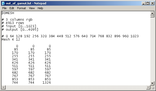
The following is an example of a 3D Mesh LUT.
 "Show full-size image")
The following format is used for 3D Mesh LUTs.
 "Show full-size image")
|
|
|
|
|
|
In this example, the 3D Mesh LUT has an input bit depth of 4 bits and an output bit depth of 12 bits. You use the input value to calculate the RGB triplet to be 17*17*17 (where 17=2^4+1 where 4 is the input bit depth). The first triplet is the output value at (0,0,0);(0,0,1);...;(0,0,16) r,g,b coordinates; the second triplet is the output value at (0,1,0);(0,1,1);...;(0,1,16) r,g,b coordinates; and so on. You use the output bit depth to set the output bit depth range (12 bits or 0-4095).
3D LUTs are highly accurate in measuring the characteristics of a specific monitor--they cannot be used on other monitors. You should update 3D LUTs as often as necessary to maintain an accurate display environment. No further monitor calibration is necessary. See Applying 3D Mesh LUTs.
You colour grade all the shots in your project in either logarithmic or linear colour space. The colour grading toolsets are dependant on the colour space you select. In Log mode, the toolset is designed for digitized film images originating from a datacine conversion process. In Linear mode, the toolset is designed for images that contain linear data.
If you want to use a logarithmic image in Linear mode, you can linearize it by creating a Log to Lin conversion LUT with the LUT Editor. See Linear Mode: Creating Conversion LUTs.
Note: In Log mode, no conversion is necessary on input since you are working on digitized film images in logarithmic colour space.
Because different facilities may be set up differently, there are many monitor calibration scenarios, particularly if you are working with film images. The following workflow scenarios are guidelines for setting up the display environment that you need.
The recommended steps involved in setting up the proper display environment are as follows.
| Step: | Refer to: |
| 1. Adjust the black level and picture settings of the graphics monitor. | Adjusting Black Level and Picture Settings. |
| 2. Select the colour space you intend to use for the project--logarithmic or linear. | Selecting the Project Colour Space. |
| 3. If you are using a colourimeter, automatically calibrate the monitor. | Calibrating the Monitor Automatically. |
| 4. If you do not have a colourimeter, manually calibrate the monitor. | Calibrating the Monitor Manually. |
| 5. If your video card is set to Dual-Head mode, set LUTS for each monitor. | Calibrating for Dual-Head Mode. |
| 6. Select and compare up to three Print LUTs obtained from your lab to determine which best calibrates the display with the printer. | Applying Print LUTs for Viewing. |
If you are applying a 3D LUT, see Applying 3D Mesh LUTs.
Note: Before you set up the proper display environment, make sure the graphics board is set to the supported resolution. See the Autodesk Lustre Software Installation Guide for your platform.
| |