Sets the options that control the modeling of NURBS curves and surfaces, including tolerances and units of measure.
Construction Presets
-
-
Copy the highlighted settings profile to a new profile.
If you want to change some of the settings in one of the presets (for example, ), make a copy of the preset profile, then edit the copy.
-
-
Delete the highlighted settings profile.
You cannot delete the preset settings profiles.
-
-
Click a profile to use the settings in that profile.
The preset profiles (for example, ) contain the settings needed for best compatibility with various CAD systems.
Units
Linear Unit options
-
-
Check this box to show sliders for the unit choices (, , and ).
Use the scale factor sliders to change a unit from whole to fractional or multiple units. For example:
- Set the to .
- Set the slider below the box to 0.125.
- The sub unit is now eighths of an inch rather than whole inches.
-
-
The unit of measurement for all linear measurements (in locators, on the prompt line and in windows).
-
-
The intermediate level of linear units.This is the unit of the second number when you type numbers using the m:s or m:s:p form on the prompt line. This unit is only used in keyboard input.
-
-
The smallest level of linear units. This is the unit of the last number when you type numbers using the m:s:p form on the prompt line. This unit is only used in keyboard input.
-
-
Set the grid spacing to 1.0 of the current (taking into account the scaling factor, if set).
Angular Unit options
-
-
Check this box to show sliders for the unit choices (, , and ).
Use the scale factor sliders to change the different units from whole to fractional or multiple. For example:
- Set the to .
- Set the slider below the box to 0.5.
- The sub unit is now half minutes rather than whole minutes.
-
-
The unit of measurement for all angular measurements (in locators, on the prompt line and in windows).
Choose (degrees), (minutes), (seconds), or (radians). The default is degrees.
-
-
The intermediate level of angular units.This is the unit of the second number when you type numbers using the m:s or m:s:p form on the prompt line. This unit is only used in keyboard input.
Choose (degrees), (minutes), (seconds), or (radians). The default is minutes.
-
-
The smallest level of angular units. This is the unit of the last number when you type numbers using the m:s:p form on the prompt line. This unit is only used in keyboard input.
Choose (degrees), (minutes), (seconds), or (radians). The default is seconds.
Tolerances
Fitting
-
-
The value and units of the maximum distance allowed between two points for the system to consider them coincident (occupying
the same space).
- For surface creation tools such as and , this value controls the accuracy of the fit of the surface edge to the construction curves.
- For fillet surfaces, this value controls the positional accuracy of the fillet surface.
- For the tool (used to stitch surfaces into a shell), this value determines which sides to check for gaps. However, the gap is actually
checked against the tolerance (see below). If the gap is within the tolerance, the sides are joined.
-
-
The sampling rate for curve fit constraints such as and .
-
-
The maximum number of spans to create when building surfaces.
- If a rebuild operation on a curve or surface requires adding more than the , the operation is cancelled.
- If maintaining continuity requires adding more than the , the continuity will not be achieved.
Continuity
-
-
The maximum distance allowed between two curves or two surfaces for the system to consider them contiguous (touching).
- For the tool, this value controls whether two edges will be joined when stitching surfaces into a shell.
- For the tool, this value controls whether common edges pass the check for gaps.
-
-
The maximum angle allowed between two surface normals for the system to consider the normals pointing in the same direction.
A smaller value gives better continuity, but usually requires tools to add more spans to the surface.
-
-
The maximum deviation allowed in curvature.
A smaller value gives better continuity, but requires tools to add more spans to the surface.
Curve on Surface/Trim
-
-
The maximum deviation allowed between the original curve-on-surface and trim edges.
-
-
The maximum distance allowed between endpoints of different curves-on-surface for the system to consider them continuous for
the purposes of defining a trim region.
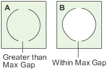
In example A, the gap between the two curves-on-surface is greater than , so the curves do not define an area.
In example B, the gap between the curves-on-surface is within , so the curves define an area for the purpose of trimming.
Rational Flags
Note
Do not turn these options on unless you understand what rational geometry is and why you need it. In most cases, rational
geometry is slower and harder to model with.
-
-
Create new primitives using rational geometry.
-
-
Create new fillets and rounds (that is, surfaces created by the and tools) using rational geometry.
-
-
Create all other new curves and surfaces (that is, all curves and all surfaces that are not primitives, fillets or rounds)
using rational geometry.
Fonts
-
-
Choose a value from the pop-up menu to adjust the size of the font used in the modeling windows for annotations and such text.
-
-
Choose either or . Fixed size will display at a constant size; Scale will change based on Dollying and Zooming.
 .
.
 , Evaluate > Continuity > Surface Continuity
 , and Evaluate > Check Model
 .
.