Trims a surface by removing (actually hiding) any part of the surface bounded by curves-on-surface. This lets you create complex edges and holes in NURBS surfaces. You can also split up (divide) a surface into multiple surfaces.
Trimming a surface involves trimming back to existing curves-on-surface. You can either project curves on the surface(s) while inside the Trim surface tool (see workflow below), or create curves-on-surface before using the Trim surface tool.
See the following sections for more information:
You can trim more than one surface at a time, using one or more projected curves.
 ❒.
❒.
 key to pick more than one surface, or use a pick box.
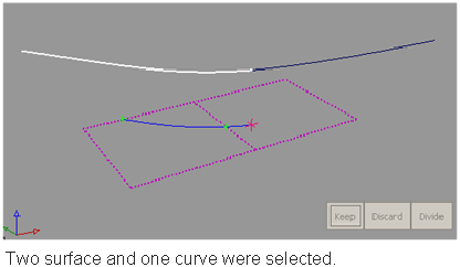
The surfaces and curves can be selected in any order, but the first object selected must be a surface.
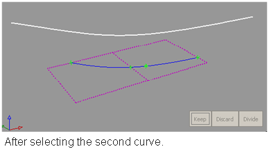
As you select surfaces and curves, the curves are automatically projected onto the surfaces, and the corresponding trim curves are displayed on the surfaces.
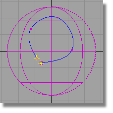
Crosshairs appear on the selected regions. To move a crosshair, click it and drag.
If those region selectors appear too large or too small on your geometry, you can adjust their size by using the Region Selector U Size and V Size sliders in the control window.
The curves-on-surface update.
If you choose Picked, you must then pick a vector object along which to project. (See Create or edit a reference vector.)
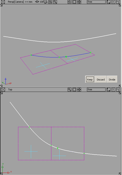
Keep: Keeps the regions selected in step 5, and discards the rest.
Discard: Discards the regions selected in step 5, and keeps the rest.
Divide: Divides the selected regions from the others (making separate trim surfaces) but keeps all the regions.
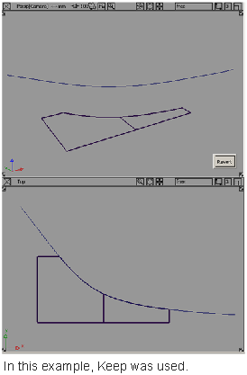
You are left within the tool with all your selections intact, so you can adjust your selections and trim again.
I can’t trim a surface because the curves-on-surface are outside tolerance?
To change the tolerances governing trim operations, choose Preferences > Construction Options and open the Curves On Surface/Trim section.
Trim Curve Fit controls the accuracy of the trim boundaries created using the trim tool.
Max Gap Between Curves is the maximum gap allowed between the endpoints of two curves-on-surface (or a curve-on-surface and a surface edge) to consider them closed when defining a trim region.
A successful trim curve is shown with a green marker where the ends of the curve join.
An unsuccessful trim curve — as in this case, where a gap exists — has the two ends of the curve highlighted in yellow to call attention to the gap region.


