


The Check model tool lists possible problems with your model that can affect data transfer to other software packages.
Show a list of modeling problems
 ❒.
❒.
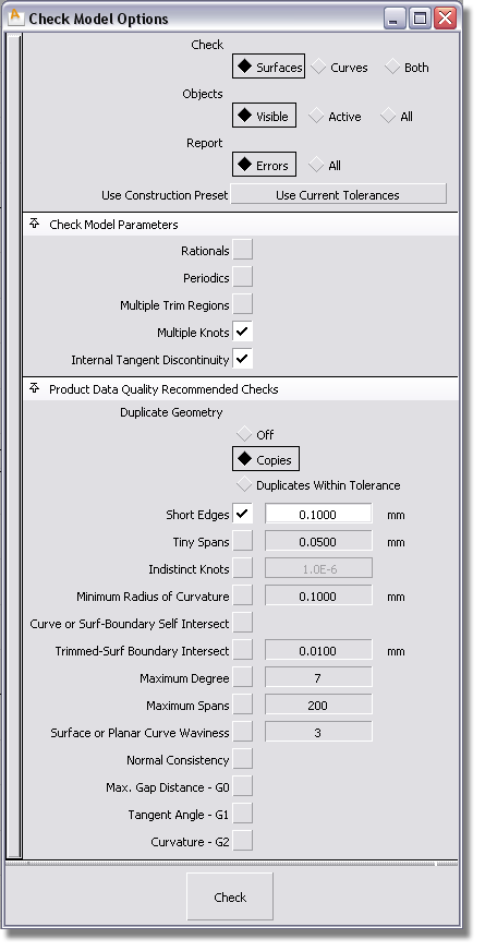
In the Check Model Options window:
These correspond to the Construction Presets available from Preferences > Construction Options. Select Use Current Tolerances to use whatever preset is already selected in the Construction Options window (indicated by a white arrow).
for more information on the different checks.
A special section called Product Data Quality contains checks that apply specifically to making a model compliant with the VDA-4955 and SASIG PDQ guidelines, so that it can be better handled by other packages such as NX, Catia, Pro/E, and so on.
See Prepare a model for import into CAD systems for more information.
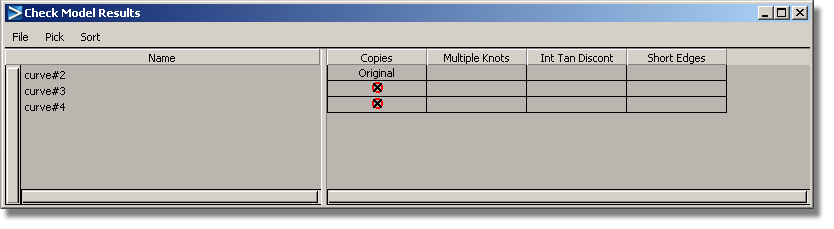
The resulting check data is displayed in a window organized as a table. Geometry that fails a given check will display a mark in the corresponding column.
See View the data in the report window
Check for duplicate curves or surfaces
You can check for both copies (exact duplicates), and duplicates within a given tolerance. Copies have the same CVs, same knots, and same degree (such as geometry created with Edit > Copy and Edit > Paste ).
This is the fastest of the two methods.
The report window displays a column titled Copies tohelp you identify all the copies. If Report is set to All, the original geometry is identified by the word “Original” in the column.
Checking for duplicates within a given tolerance
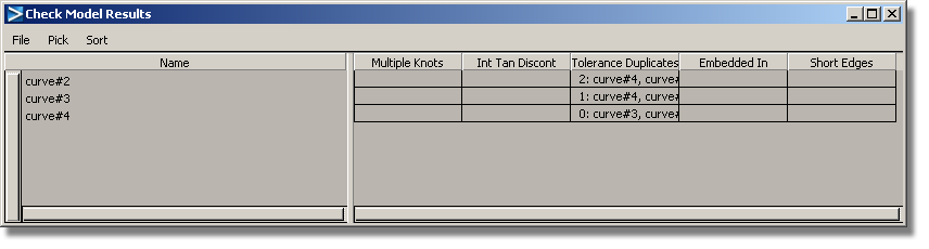
The report window displays two columns titled Embedded In and Tolerance Duplicates tohelp you identify all the duplicates. The duplicates prefixed by “0” in the Tolerance Duplicates column are considered the originals.
Check continuity between curves or surfaces
Tolerances for these continuity checks are found in the Tolerance:Continuity section of Preferences > Construction Options and correspond to the construction preset selected in the Check Model Options window.
For the G0 test to be successful, you must also ensure that the Topology Distance tolerance (Tolerances:Topology section under Preferences > Construction Options) is larger than the Maximum Gap Distance.
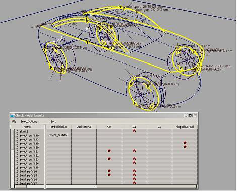
The report window displays columns titled G0, G1 and G2 with marks indicating failure. If geometry fails the G0 test, higher continuity tests for G1 and G2 will not be performed. Similarly, if geometry fails the G1 test, continuity test for G2 will not be performed
In the viewing window, the boundaries that failed the continuity tests are shown as thick yellow lines with a letter identifying the type of discontinuity (P = positional, T = tangent, C = curvature).
The report parameters are tolerance values above which certain types of checks will not be executed.
Check consistency of orientation of surface normals
The Topology Distance tolerance is used to determine which surfaces are topologically adjacent and should have their normals checked as a group.
It is found in the Tolerances:Topology section of Preferences > Construction Options and corresponds to the construction preset selected in the Check Model Options window.
The report window displays a column titled Flipped Normal tohelp you identify the surfaces with inconsistent normal directions. In the viewing window, the inconsistent normals are shown as white arrows.
This check enables you to identify curves and surfaces that exceed a user-defined degree. The default value for maximum degree is 7.
The report window displays a column titled Degree which contains the degree of curves and/or surfaces that failed the test.
Check for minimum radius of curvature
This check enable you to identify surfaces (including trimmed surfaces) that exceed a user-defined curvature radius.
The report window displays a column titled Min Radius of Curv which contains the minimum radius found on surfaces that failed the test.
Check for surface or planar curve waviness
This check enables you to identify surfaces or planar curves that have more than a certain number of inflections (change in curvature sign) per span (1 is the default) or over their entire length or width (3 is the default).
The report window displays a column titled Waviness with marks indicating failure.
This check enables you to identify curves and surface boundaries that are shorter than a user-defined value. This helps find geometry that may be problematic when used in certain operations, or may not be recognized as valid geometry in downstream CAD systems.
See Prepare a model for import into CAD systems for more information.
The report window displays a column titled Short Edges which contains the number of short edges on geometry that failed the test.
This check enables you to identify curves that are not planar. In the Check Model Settings option window, set the Check option to Curves or Both.
The report window displays a column titled Non-Planar Curve with marks indicating failure for the objects listed in the left-hand column.
Check for indistinct knots or tiny spans
This check enables you to identify curves and surfaces whose interior span/isoparm configuration (distance between adjacent isoparametric curves) results in knots being too close (indistinct knots), or in the segment or patch size being too small (tiny spans).
The indistinct knot criterion is violated if two adjacent knots are non-multiple (not exactly equal), but within a user supplied tolerance in the curve or surface parameter space.
Multiple knots do not violate this criterion - a separate check already exists for finding curves and surfaces with multiple knots.
The tiny span criterion for the minimal size of NURBS segments is violated if the segment length (or the length of both opposing patch segments for surfaces) is smaller than a user supplied distance tolerance.
The report window displays columns titled Indistinct Knots and Tiny Spans which contain the number of occurences of indistinct knots and tiny spans respectively, in the geometry that failed the test.
Check for maximum number of spans
This check enables you to identify curves and surfaces that contain a number of spans exceeding a user-defined value.
The report window displays a column titled Spans which contains the number of spans in the geometry that failed the test.
This check enables you to identify curves, surface boundaries, or trimmed surface boundaries that contain interior self-intersections. A self-intersection refers to the curve or surface boundary intersecting itself at one or more locations that are not both endpoints (see pictures below).
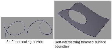
The report window displays a column titled Self-Intersecting with marks indicating failure for the objects listed in the left-hand column.
Check for intersection of trim boundaries
This check enables you to identify trimmed surfaces containing boundaries that intersect other boundaries on the same surface, within a user-defined tolerance (see picture).
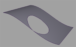
The report window displays a column titled Trim Bndy Intersect with marks indicating failure for the objects listed in the left-hand column.
View the data in the report window
 on a row to highlight the object in the view windows.
 to select multiple lines.