Creating and editing cross sections allows you to "bulge" the mesh. The Bulge Editor is an alternative to using the Bulge sub-object level to create and edit bulge angles. The difference is that the Bulge Editor allows you to create, select, and edit cross sections in schematic Cross Section and Profile views. Using the Bulge sub-object level, creating and editing bulge angles takes place in the viewports. All of the parameter changes you make in the Bulge Editor are also reflected on the mesh in the viewports.
On the Modify panel, you access the Bulge Editor from the Physique rollout, from the Bulge rollout at the Bulge sub-object level, or from the Link Settings rollout at the Link sub-object level.
Using an Animation to Preview Limb Orientations
For easier creation of bulge angles, you should create a simple animation that moves the limb into extreme orientations. In the case of the human arm, you might set keyframes with the arms down against the body; extended to the sides; bent at the elbows; and finally, more relaxed with the hands touching the shoulders. By scrubbing the time slider, you can easily choose one of many intermediate or extreme orientations. This saves time when you create Bulge Angles, because you won't need to exit Physique to manipulate the skeleton to change the orientation of the mesh. You can create and set multiple Bulge Angles without ever leaving the Bulge Editor or Bulge sub-object level.
To create a new bulge angle using the Bulge Editor:
 (Bulge Editor) at the top level of the Physique modifier, or at the Link or Bulge sub-object level.
 click to select a link.
 (Insert Bulge Angle).
Physique creates a new bulge angle. The number of the bulge angle name in the Current Bulge Angle field increments.
 (Insert CS Slice). Click the Profile view to create and position a cross section.
 rotate the joint to the desired angle.
This is most easily done by creating a preview animation, as described in Using an Animation to Preview Limb Orientations: just move the time slider to a frame that has the angle you want. Otherwise, you will have to exit the Bulge sub-object level, select the appropriate limb, and rotate it. For example, to bulge the biceps on a biped, you might rotate the biped forearm to ninety degrees.
As you scale or move control points in the Cross Section view, the mesh "bulges" in the viewports.
 (Set Bulge Angle).
Physique saves the current angle of the joint.
When the joint angle is reached, the mesh bulges. By default, Physique creates one bulge angle when it is first attached to the mesh. So to make an arm or leg that bulges when biped joints are rotated, you need to create and set only one additional bulge angle.
To change a bulge angle value:
Rotate a biped limb or use the time slider to move to a frame that has the limb rotated correctly.
(Set Bulge Angle).
The angle of the joint is set for the displayed bulge angle. When the biped limb rotates to this angle, the mesh bulge effect is at full strength.
To choose a specific bulge angle for editing:
The Bulge Editor’s Cross Section and Profile views update to show the cross sections associated with the newly selected bulge angle.
 (Delete Bulge Angle).
(Insert CS Slice).
(Delete Bulge Angle).
(Insert CS Slice).
 (Delete CS Slice).
To make a cross section the active cross section:
The selected cross section displays in Cross Section view. You can change its shape by selecting and editing control points in Cross Section view. This will bulge the mesh at the location of the cross section.
To select multiple cross sections:
You can change parameters for multiple cross sections by selecting them and then adjusting parameters in the Cross Sections panel.
 (Select And Translate CS).
To move cross sections along the link:
Moving a cross section repositions where on the mesh a bulge occurs.
(Select And Translate CS).
To copy and paste cross sections:
 (Copy Selected CS).
 (Paste Selected CS).
The cross section you pasted now has the shape of the cross section you copied.
To change the shape of a cross section:
 move,
move,  scale, or
  rotate the cross section's control points.
 Select, Scale, and Rotate Control Points
Lets you select, scale, and rotate control points of a cross section in the Cross Section view.
This is comparable to using the Move transform on geometry in viewports. Control points are simultaneously scaled and rotated around the link, which in effect "moves" them.
Select a cross section in the Profile view first. Then select and move control points in the Cross Section view to change the bulge.
Select and Rotate Control Points Select and Scale Control Points Draw Control Points
Lets you add control points by drawing freehand in the Cross Section view. The shape of the bulge changes based on the shape you draw.
In the Cross Section view, you can draw the cross section interactively, placing control points at each resolution step. You can freeze existing control points by selecting them in the Cross Section view and holding down the Ctrl key as you draw.
 Insert Control Points
 Delete Control Points
 Previous Link and Next Link
 Mirror Selected CS Select and Translate CS Insert Cross Section Slice Delete Cross Section Slice Copy Selected CS
Copies the selected cross section.
You can copy a cross section from one link to another link. Create a new bulge angle with an appropriate cross section in the target link first, then copy the cross section parameters form the source cross section, select the target cross section, and click Paste Selected CS.
Paste Selected CS Set Bulge Angle Insert Bulge AngleAdds a new bulge angle for the selected link.
The Current Bulge Angle field displays a bulge angle name with the number incremented. You can enter a descriptive name for any new bulge angle; for example, Arm at 90.
By default, one initial bulge angle is created when Physique creates links. Only one additional bulge angle will allow you to bulge the mesh. You can create more bulge angles for further control, if you like.
Delete Bulge Angle Select Nearest Bulge Angle
When on, selects the bulge angle nearest to the current joint angle.
If a joint bends over time, you can use this button in conjunction with the time slider to select a bulge angle. If you play the animation, you can see the Current Bulge Angle field change to reflect the bulge angle nearest to the current angle of the selected link and its child (if two or more bulge angles for the limb exist).
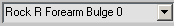 Current Bulge Angle field and drop-down list
Displays the current bulge angle. You can choose a bulge angle from the drop-down list to edit the bulge or change its name. To change the name, simply enter a new one in the edit field.
When you create a new bulge angle by clicking Insert Bulge Angle, this field displays the default bulge angle name, which is the previous name with its sequence number incremented.
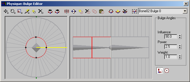
Cross Section view displays an outline of the active cross section. In Profile view, the active cross section is shown in a bright red color. In Cross Section view, you can edit cross sections to bulge the mesh.
These are the elements of the cross section display:
Display as gray lines that surround the link radially. Control points snap to these lines as they are positioned.
You can increase or decrease the resolution by changing the Resolution setting. This control is on the Bulge rollout in Bulge Sub-Object. The Cross Section view, however, always displays 36 resolution lines.
The bright yellow radius indicates the orientation of the “slice” shown in profile view. Profile view always shows a vertical profile of Cross Section view, indicated by the green dots at the top and bottom of the view, just outside the circle that contains the resolution lines. By default, the orientation bar is level at 3 o'clock. You can change the Profile view orientation by dragging the end of the orientation bar (the cursor changes to a miniature cross section). This lets you view different angles of the bulge in Profile view.
Use Profile view to select, move, and copy cross sections on the selected link and its child. Highlight a cross section in Profile view to display and edit it in Cross Section view.
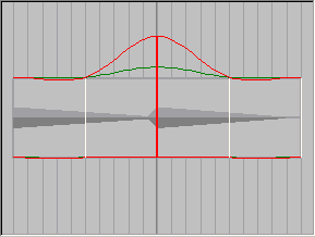
Profile view is a schematic profile of two links. The currently selected link is on the left, and its child link is on the right. If the selected link is an end link, the outline of the right half of the Profile view turns gray.
Cross sections are shown as vertical bars across the profile. The active cross section is red. Unselected cross sections are white. Cross sections that are selected but not active are dark red.
You can use a rectangular selection region or Ctrl+click to select multiple cross sections. Although only one cross section at a time is active in Cross Section view, you can use the Cross Sections panel to change parameters for multiple cross sections.
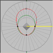
Profile view shows a profile of the bulges you create. As in Cross Section view, the control spline is red and the deformation spline is green.
The profile is always a vertical profile of the Cross Section view. You can drag the orientation bar in Cross Section view to change the angle of the profile.
To insert a new cross section, turn on Create CS Slice and then click Profile view to set the cross section's location.
You can use the Draw tool in Profile view to change the control spline by freehand drawing. Drawing updates the cross section
shapes.
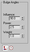
At the right of the Bulge Editor are two panels for setting parameters. Use the Bulge Angles panel to change bulge settings for the currently active bulge angle.
 Bulge Angles
The range of angles through which the bulge influences the skin. Range=0 to 180. Default=90 degrees.
For example, if you’ve set a bulge angle for the joint at 90 degrees, an Influence value of 40 means that the bulge effect begins to appear when the rotating joint reaches 50 degrees (90 minus 40) or 130 degrees (90 plus 40).
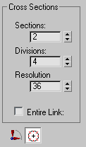
At the right of the Bulge Editor are two panels for setting parameters. Use the Cross Sections panel to change the cross section settings for a particular link.
 Cross Sections
Sets the number of cross sections for the selected link.
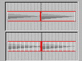
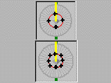
Above: Sections=1
Below: Sections=8
When on, selects all cross sections for all bulge angles in the selected link. Use this to globally change parameters for all cross sections on a link.
Entire Link also affects Copy Selected CS and Paste Selected CS. While Entire Link is on, Copy Selected CS copies all cross sections for all bulges, and Paste Selected CS pastes all cross sections for all bulges. Entire Link is useful for copying all the bulges from one arm or leg to another.


 Modify panel