There are two sets of commands for generating surfaces and polygon meshes from curves:
The first group of commands in the Create  Surf. Mesh menu on the Model toolbar create NURBS surface meshes consisting of one subsurface.
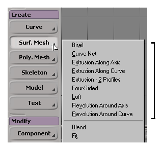
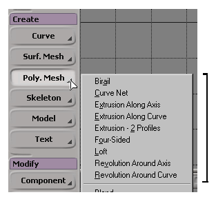
The first group of commands in the Create Poly. Mesh menu on the Model toolbar create polygon meshes.
The commands and the procedures on these two menus are the same. The only difference is the type of object that is created.
The sections that follow include some basic information that is common to all or most of the operators that generate objects from curves.
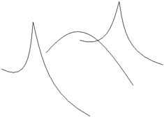
In the procedures that follow, you are not limited to curve objects for building surfaces. You can select any combination of isolines, knot curves, boundaries, surface curves, and trim curves as well as curve objects. For example, you can create a loft surface that joins two surface boundaries while passing through other curves.
Most of the generators, like extrusion, revolution, and so on, do not work with curve objects composed of multiple subcurves such as those obtained from text or imported EPS files — what happens is that only the first subcurve is used. However, you can extract the subcurves as separate curve objects first, as described in Extracting Curve Segments.
Most of the operators that generate objects from curves, like extrusion, revolution, and so on, use a standard set of controls to determine the subdivisions (knot curves) of the result.
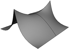
If Subdivision Type is Per Span, the basic subdivisions are based on the "natural" subdivisions as determined by the shapes of the inputs. You can subdivide each segment further using the U and V span sliders.
In this case, discontinuities resulting from multiknots in the inputs are preserved in the generated objects.
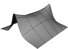
If Subdivision Type is Absolute, you can use the U and V abs sliders to set the exact number of subdivisions in the resulting object.
However, the result is automatically reparameterized and discontinuities are not preserved.
When you build a NURBS surface, the result can be linear or cubic in either U or V, depending on whether it is built from linear or cubic inputs in each direction. For example, if you use Curve Net (see Using Curve Net) and all your U input curves are cubic and all your V input curves are linear, the result is cubic in U and linear in V.
If you use a mixture of cubic and linear inputs in the same direction, then the result will always be cubic in that direction.
For those operations where you specify inputs for only one direction, like Loft, Extrusion Along Axis or Revolution, the V direction of the result is always cubic.
In all cases, you can use Fit Surface to create a new surface with the degrees you desire — see Fitting Surfaces [Surface and Curve Modeling].
The direction in which curves are drawn determines the direction in which the normals point on the resulting object. Remember to draw curves counterclockwise for the proper alignment of normals.
If the normals of the resulting object are pointing in the wrong direction, you can invert a surface as described in Inverting Normals, invert a polygon mesh as described in Inverting Auto Normals, or invert one or more of the input curves as described in Inverting Curves.
Whenever you generate a new object from other input objects, you can manage the inputs, for example, you can hide or delete them. See Managing Generator Inputs.
When you generate surfaces or polygon meshes from curves, you can automatically generate explicit UV coordinates for textures. The UVs created in this way are evenly spaced according to the number of segments (edges or knot curves) in each direction.
The UV generation is "live" — if you change the number of subdivisions in the generator operator or modify the input curves, the UV coordinates are automatically updated. If you change the number of subdivisions after you have manually edited the UVs, you probably won't get desirable results because the UV indices have changed. If you freeze the UV coordinates, the generator operator is frozen as well.
For more information about texture projections and UV coordinates in general, see What's in a Texture?.
 Except where otherwise noted, this work is licensed under a Creative Commons Attribution-NonCommercial-ShareAlike 3.0 Unported License