You can use other objects in your scene to create curves. A modeling relation exists between the new curve and the input objects used to define it (unless, of course, you are modeling in immediate mode). Modifying the originals in any way also modifies the created curve.
In addition, you can select the created curve and open the property editor of the corresponding operator to adjust its parameters. The modeling relation exists until you freeze the generator operator (the bottom node in the created curve's geometry stack).
You can extract a linear curve from edges on a polygon mesh object.
Select some edges on polygon mesh objects.
Choose Create  Curve Extract from Edges.
New curves are created and the Extract Edge Loop property editor opens. By default, there is a single linear span for each edge in the original polygon mesh.
Adjust the Mesh Subdivision Level. Higher values produce smoother, denser curves, as if the original polygon mesh was subdivided using the Catmull-Clarke rule.
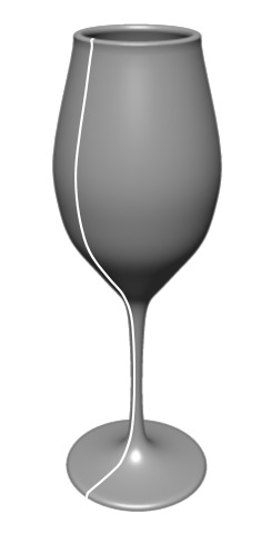
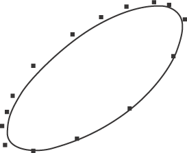
Select one or more isoline, knot curve, boundary, surface (projected), or trim curve on a surface.
Choose Create Curve Extract from Surface from the Model toolbar.
If you did not select any curves to extract in step 1, you are prompted to pick a curve now.
By default, the picking session selects a U isoline with the Rectangle tool, but you can change the filter using the buttons
on the Select panel and you can change the tool using the commands on the Select Tools menu or the keyboard equivalent (for example, F10 for the Raycast tool).
A new object is created for each selected curve and the Extract Curve from Surface property editor opens. The curves are automatically closed if the surface is closed in the corresponding direction; otherwise the curves are open.
If desired, use the controls on the Surface Curve Adaptor page to adjust the extracted curve.
In the case of assembled surface meshes, the Extract on Whole Mesh option lets you extract the curve across multiple subsurfaces. For more information about surface meshes in general, see Surface Meshes.
Some curve objects, particularly text and imported EPS curves, contain multiple subcurves. You can extract subcurves to create new curve objects.
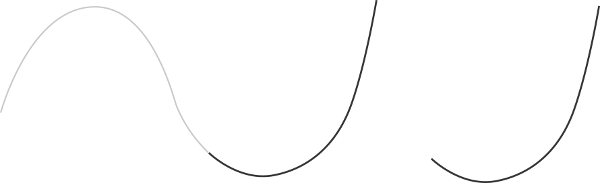
You can fit one curve onto another. This is useful for cleaning curves that were drawn with the Sketch tool and for increasing or decreasing the number of points on a curve. You can specify the number of points and the degree of the new curve. The parameterization of the new curve is uniform.
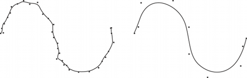
The original sketched curve and a new curve fitted onto it.
Choose Create Curve Fit on Curve from the Model toolbar.
If you didn't select a curve in step 1, you can pick one now.
A new curve is created and the Fit Curve property editor opens. Set values as desired:
Subdivisions controls the number of control points on the created curve and (indirectly) how accurately the new curve follows the original.
Degree controls whether the curve is a Cubic or Linear NURBS.
Close does not create a true periodic curve ; instead, it superimposes the last point on the first.
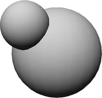
You can create a curve that represents the intersection of two surfaces. For best results, first make sure that the surfaces have the same parameterization. For more information, see Reparameterizing Surfaces.
Choose Create Curve Intersect Surfaces from the Model toolbar.
If you didn't select both surfaces in step 1, you can pick them when prompted.
This creates a curve and the Intersect Surfaces property editor opens.
If the two surfaces intersect in multiple places, the new curve will be composed of multiple disjoint segments. However, the curve is one single 3D object as shown in the explorer.
If the curve cannot be calculated, for example if the two surfaces do not intersect, the result is a unit circle at the global origin.
You may need to adjust the tolerance parameters for the curve.
Blending two curves creates a third curve that joins the two originals. Unlike Merging, this feature simply joins two existing curves without creating a new curve.
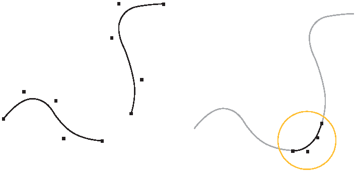
The orginal curves and the new blend curve between them.
Choose Create Curve Blend from the Model toolbar.
This creates a third curve and the Blend Curves property editor opens.
If necessary, adjust the parameters of the blend curve. For more information, see Blend Curves Property Editor [Properties Reference].
If you selected curve objects instead of their boundaries, the blend curve may not be connected at the desired ends. Use the controls in the Curve Point Adaptor pages to adjust the start and end points.
As an alternative to blending curves, you can merge them as described on Merging Curves.
You can create a curve that is a fillet, or smooth blending arc, between two curves. Depending on how the curves are drawn and the options you set, the two original curves do not need to intersect.
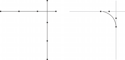
Two intersecting curves and the fillet curve between them.
Choose Create Curve Fillet Intersection from the Model toolbar.
If you didn't pick both curves in step 1, you can pick them now.
An arc is drawn from the beginning of the first curve selected to the end of the second and the Fillet Curves property editor appears.
Adjust the Radius and the Tolerance. If no fillet can be created with the specified settings, a unit circle is created at the origin.
To change where the fillet is created on the crossing curves, invert one or both curves using Modify Curve Inverse.
For a non-circular fillet, you can move points or otherwise deform the created curve. The modeling relation with the original curve remains, so that if you modify the original curves the deformed fillet changes accordingly.
As an alternative to filleting curves, you can blend curves as described in the previous section or merge them as described in the next section.
Merging two curves creates a third curve that spans the original two. Unlike Blending, this feature actually creates an extra curve.
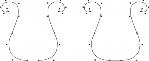
Two separate curves and a single merged curve.
Choose Create Curve Merge from the Model toolbar.
This creates a third curve spanning the originals and the Merge Curves property editor opens.
If necessary, adjust the parameters of the merged curve. For more information, see Merge Curves Property Editor [Properties Reference].
If you selected curve objects instead of their boundaries, the merged curve may not span the desired ends. Use the controls in the Curve Point Adaptor pages to adjust the start and end points.
As an alternative to merging curves, you can also stitch them as described on Stitching Curves or blend them as described on Blending Curves.
If you have animated the translation of an object, you can plot the motion of its center to generate a curve. For example, this can be used to create a trajectory curve. You can also plot the movement of a selected point or cluster.
Choose Tools Plot Curve from the Animate toolbar. The Plot Curve dialog box opens.
The Start Frame and End Frame specify the frames at which to begin and end plotting.
The Step Value controls the sampling of the generated curve. If this value is 1, a point on the curve is created for every frame; if this value is two, a point is created for every other frame; and so on.
Curve Name is the name to use for the generated curve object.
Click OK. The scene is played back and a curve is created. The original animation remains.
 Except where otherwise noted, this work is licensed under a Creative Commons Attribution-NonCommercial-ShareAlike 3.0 Unported License