


Output Clip Menu Controls
You can view the Output Clip menu in large or small form depending on which tab is selected.
When the Output, Audio, or Engineering tab is selected, both the large and small forms are available. To toggle between the large and small forms, Ctrl-swipe the bottom of the screen.
When the Deliverables or Logo tab is selected, only the large form is available, but additional Pan and Zoom controls are available.
If you are using the large Output menu with an HD clip, the menu automatically switches to the smaller form during clip output, and then switches back when output is complete. This gives you an unobstructed view of the clip during output.
Small Output Clip menu (left portion):


Large Output Clip menu (broken into three parts):
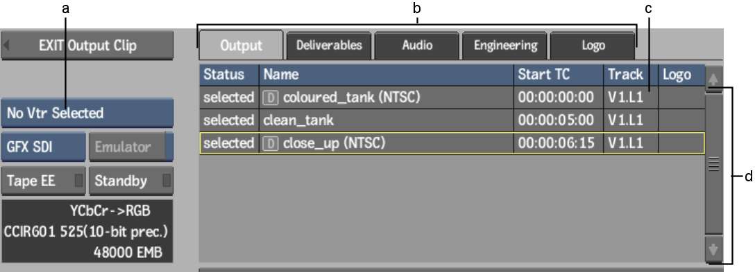
(a) Device Name box (b) Navigation tabs (c) Video Layer field (d) Output Clip list
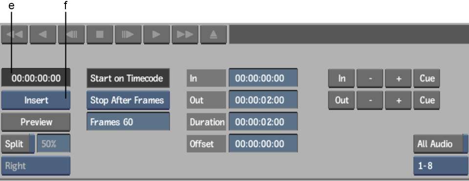
(e) Current Timecode field (f) Output box
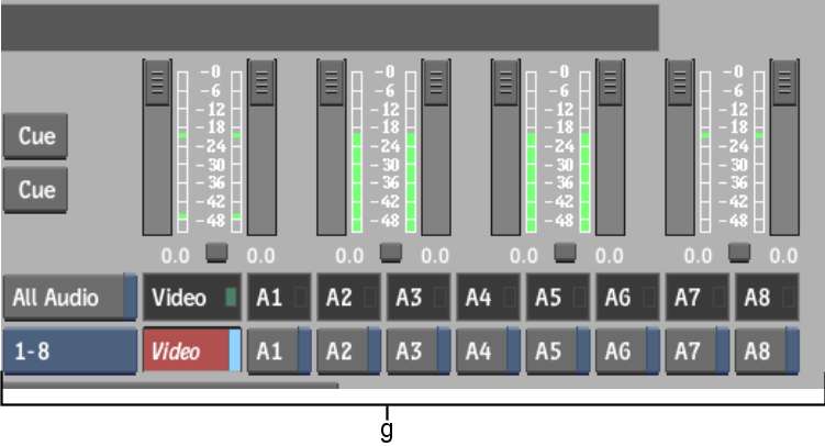
(g) Audio controls
In this documentation, the large menu is described. Differences present in the small menu are noted where applicable.
Device Name boxDisplays the options for each uncommented VTR keyword line in the software initialisation configuration file. Select the option corresponding to the VTR to which you want to output clips. See Selecting a VTR Device For Output.
Navigation tabsSwitch between different Output Clip menus.
| Select: | To: |
|---|---|
| Output | Configure the output settings described in this section. This is the default menu. |
| Deliverables | Set up Real-Time Deliverables on output, such as Letterboxes or LUTs. See Outputting Clips With a Letterbox Overlay and Clip Output Using Real-Time Deliverables. |
| Audio | Set Audio preferences. Changes are reflected in the Audio section of the Preferences menu, and vice versa. See Audio Preferences. |
| Engineering | View the output clip Engineering menu. See Setting Video Input and Output Engineering Menu Controls. |
| Logo | Set up a logo on output. See Outputting Clips with a Logo Overlay. |
Output Clip listDisplays information about the clip selected for output. If there are multiple clips, you can sort them by clicking the column headings. This changes the output sequence order. You can also edit the Timecode field in this list. See Outputting Multiple Clips. If the list includes Deliverables and you do not have the hardware required by Real-Time Deliverables, the Deliverables are greyed out. See Outputting Deliverables.
Video Layer fieldIndicates the track to output in a multi-track clip. Drag the field to browse through the video tracks and video layers. This field is red when the selected layer is not the top layer of the selected video track; this does not prevent output.
Graphics Card boxIf you have the NVIDIA Quadro FX 5600 SDI graphics card for using Real-Time Deliverables, switch between it and the standard AJA_OEM2K card using this box. See Hardware Requirements for Real-Time Deliverables.
Emulator buttonEnable to use a VTR emulator. See VTR Emulation.
Tape EE buttonWhen lit, indicates that the VTR is in E-to-E mode (electronic to electronic). This means that the VTR output is showing its input signal. When E-to-E is off, the VTR shows the contents of the tape it contains. Click this button to toggle E-to-E on and off.
Standby buttonWhen lit, indicates that the VTR is in standby mode. Click this button to toggle between on and off.
VTR Status displayIndicates the current status of the VTR. See Verifying the VTR Status.
Current Timecode fieldIndicates the current timecode of the tape in the VTR.
Output boxSwitch between insert or assemble mode. Click to perform the selected action.
Preview buttonTriggers a simulation of the output process. The VTR behaves as if it is inserting material, however no material is recorded to tape.
Split View buttonEnable to simultaneously monitor the clip selected for output and the contents of the tape. See Monitoring Video During Clip Input and Output Operations.
Start On Timecode fieldA locked field indicating that clip output begins at the timecode entered in the In Timecode field.
Stop Mode boxDetermines the stop mode for clip output.
| Select: | To output the current clip until: |
|---|---|
| Stop On Timecode | A timecode on the tape is reached (indicated in the Out Timecode field). |
| Stop After Frames | A specified number of frames is output. When you select this option, a field appears in which you enter the number of frames to output. |
In Timecode fieldIndicates the timecode on the tape at which point the clip output process begins.
Out Timecode fieldIndicates the timecode on the tape at which point the clip output process ends.
Duration fieldIndicates the duration, in timecode, between the clip output in and out points.
Offset fieldIndicates the offset, in timecode, by which the selected clip is output. For example, an offset of 00:00:00:05 indicates that the first five frames of the clip to be output are skipped. The first frame to be output is frame 5 of the clip (counting frames from 0).
In/Out Point controlsUse to enter, adjust, and cue the in and out points. See Setting Input and Output In and Out Points.
All Audio buttonEnable to output all audio channels for monitoring, even if only some audio channels are enabled for recording to tape.
Audio Channel buttonsEnable and control audio output signals. See Adjusting Audio Gain on Output Clip.