


Setting Video Input and
Output Engineering Menu Controls
Clip input and output engineering options include video I/O settings such as pre-roll, post-roll, play delay, colour space conversion, and settings that define the process by which YUV video material on a tape is converted to the RGB format used by Backdraft Conform, and vice-versa.
Each VTR device is associated with a set of default engineering settings that are specified in the software initialisation configuration file, in the VTR KEYWORD section.
When you start Backdraft Conform and set the video I/O timing for your project, uncommented VTR devices are initialized, and the settings in the Engineering menu are populated accordingly. However, if necessary, you can modify these settings on a session-to-session basis.
To change the default Engineering menu settings for a VTR device, you must edit the software initialisation configuration file. See the Autodesk Visual Effects and Finishing Configuration File Reference Guide.
Consult the following illustration (broken into three parts) and explanations of the options in the Engineering menu. These illustrations are of the Clip Input Engineering menu. The Output Clip Engineering menu contains a subset of these controls.


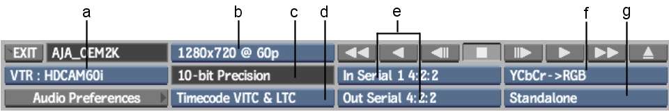
(a) Device Name box (b) Video I/O Timing box (c) Precision box (d) Timecode Source box (e) Input and Output Connection boxes (f) Colour Space box (g) Output Sync box
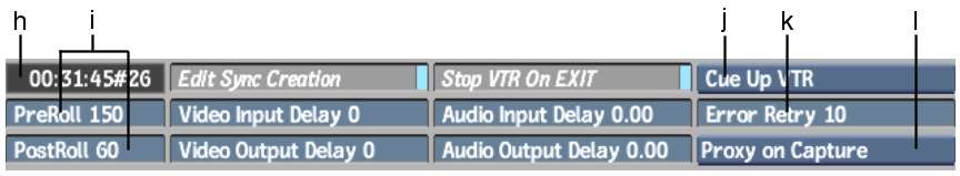
(h) VTR Current Timecode field (i) PreRoll/PostRoll fields (j) Cue Up box (k) Error Retry field (l) Proxy Box
Device name boxProvides an option for each uncommented VTR keyword line in the software initialisation configuration file. To modify settings for a specific VTR device, select the corresponding option from this box.
Video I/O Timing box Provides video timing options (resolution and frame rate) corresponding to different video formats supported by the video input/output board of the system.
Precision boxDetermines the video interface precision, or SDI bit depth used. This value cannot be changed.
Audio Preferences buttonClick to view the Audio Preferences menu. See Audio Preferences.
Timecode Source boxDetermines which type of timecode is obtained from the VTR device.
| Select: | To obtain: |
|---|---|
| Timecode VITC | Vertical interval timecode (VITC). |
| Timecode LTC | Longitudinal timecode (LTC). |
| Timecode VITC & LTC | Both types of timecode. At normal playback speed, Backdraft Conform obtains LTC, but switched to VITC when the tape is rewinding, fast-forwarding, or otherwise moving at a non-playback speed. |
Timecode VITC & LTC is the default, and recommended option. You should only have to switch to Timecode VITC or Timecode LTC if one of the timecode tracks is corrupted.
Input and Output Connection boxesDetermines the connection by which the video signal is transferred. These boxes are locked to In Serial 4:2:2 and Out Serial 4:2:2.
Colour Space boxDetermines the YCrCb colour space conversion method. See Inputting and Outputting with Headroom.
| Select: | To perform clip I/O with: |
|---|---|
| YCrCb->RGB | A standard YCrCb-RGB conversion process that clips superblack and superwhite luma (Y). Use this option for typical clip I/O processes with VTR devices. |
| YCrCb->RGB + Headroom | A YCrCb-RGB conversion process that preserves superblack and superwhite colour information. Use this option when inputting or outputting greyscale mattes or other clips where preserving extremes in the luma channel is required. |
| No Conversion | This is available when using dual link for RGB input and output. Video black and white levels on the SDI stream are mapped to black and white values in RGB on the framestore. See Inputting and Outputting with Headroom. Use this option in conjunction with 4:2:2 input and output connections to input and output 4:4:4 video in two passes (4:2:2 and 0:2:2). Third-party sparks® (in Smoke®, Inferno®, Flame®) are required to split and merge the 4:2:2 and 0:2:2 clips. |
| No Conversion + Headroom | Also available when using dual link for RGB input and output. This mode uses all levels available and preserves all but a few RGB values. See Inputting and Outputting with Headroom. Use this option with the 4:4:4 input and output connections to input clips from and output clips to a Telecine. |
Output Sync boxDetermines the output sync reference source. The reference signal may originate from several different sources. Select the source you are using from this box according to the following table.
| Source type | Available on: | Description: |
|---|---|---|
| House | All systems | A centralized analogue reference signal, originating from a sync generator, sent to the genlock port on the video board or VBOB. |
| Digital 1 and Digital 2 | Most HP® 8400s and all HP 8600s and 9400s | Same as Digital, except you can choose between two inputs: Digital 1 or Digital 2. On the HP 8400 with the AJA SD (OEM-LH) video board, only Digital 1 is available. |
| Standalone | All systems | The reference signal generated internally by the Backdraft Conform workstation. |
PreRoll fieldIndicates the pre-roll, in frames.
PostRoll fieldIndicates the post-roll, in frames.
Video Input Delay fieldIndicates the video delay on input, in frames. If this value is incorrect, the result clip when you click Frame Grab in the Input Clip menu does not match the frame you see in the preview window.
Video Output Delay fieldIndicates the video delay on output, in frames. If this value is incorrect, the clip you output does not get recorded to the proper place on the tape.
Audio Input Delay fieldIndicates the video delay on input, in frames.
Audio Output Delay fieldIndicates the video delay on output, in frames.
Stop VTR on EXIT buttonWhen enabled, sends a stop command to the VTR when you exit the Input Clip, Output Clip, Auto-Capture, or Archiving menu. For example, if the VTR is playing a clip, or if it is cueing to an in point, the transport operation in-progress is interrupted.
Cue Up boxDetermines the speed of the cueing process.
| Select: | To cue up the VTR: |
|---|---|
| Cue Up VTR | Using the internal cueing algorithm of the VTR. |
| Cue Up Fast Forward | Using Backdraft Conform. Use this option if Cue Up VTR is too slow for far cue points, such as on the betacam SP. |
Error Retry fieldIndicates the number of times Backdraft Conform retries failed input or output processes.
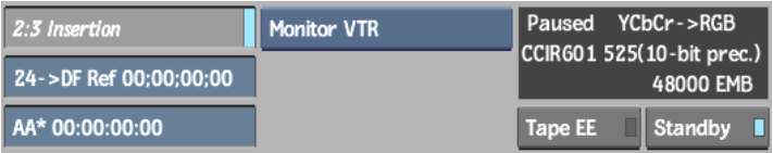
2:3 Removal/Insertion buttonEnables automatic, real-time 2:3 removal on output and insertion on input. This is only available when the VTR is set to 29.97i or 59.94i.
Edit Sync Creation buttonAutomatically create edit sync groups for clips with audio channels on input. See Creating Edit Sync Groups for Multiple Video Tracks.
Proxy box Determines proxy management when inputting clips.
| Select: | To generate: |
|---|---|
| Proxy in Post | Proxies as a post-processing step |
| Proxy on Capture | Proxies during capture |
Generating proxy during capture is the quickest method. Depending on hardware configuration of your system, capture may be performed in real time with playback. Some extra required processing, however, may prevent the graphics board from updating the image window and broadcast monitor in real time, so you may not be able to view the clip being played as it is captured.
Monitor box Set this to Monitor VTR or Monitor Output. In Monitor VTR mode, the signal coming back from the VTR is displayed, and video may be appear to be late compared to the audio. In Monitor Output mode, the signal being output to tape is displayed, and the video and audio should be in sync.