Contains the main controls for the appearance of an Arch & Design material.
From a usage perspective, the shading model consists of three components:
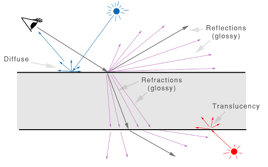
The Arch & Design material shading model
Direct and indirect light from the scene cause diffuse reflections as well as translucency effects. Direct light sources also create specular highlights.
Ray tracing is used to create reflective and refractive effects, and advanced importance-driven multi-sampling is used to create glossy reflections and refraction.
The final surface reflectivity is in reality caused by the sum of three components:
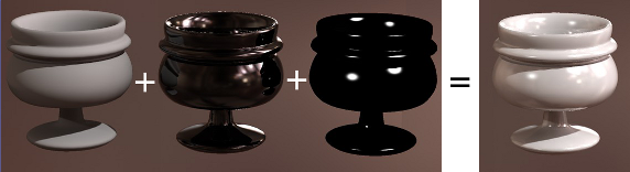
Diffuse, reflections, and highlights
In the real world, highlights are just glossy reflections of the light sources. In computer graphics, it’s more efficient to treat these separately. However, to maintain physical accuracy, the material automatically keeps highlight intensity, glossiness, anisotropy, and so on, in sync with the intensity, glossiness, and anisotropy of reflections. Thus, there are no separate controls for these, as both are driven by the reflectivity settings.
One of the most important features of the Arch & Design material is that it is automatically energy conserving. This means that it makes sure that diffuse + reflection + refraction <= 1. In other words, no energy is “magically” created, and the incoming light energy is properly distributed to the diffuse, reflection, and refraction components in a way that maintains the first law of thermodynamics.
For example, when adding reflectivity, the energy must be taken from somewhere; hence, the diffuse level and the transparency will be automatically reduced accordingly. Similarly, adding transparency happens at the cost of the diffuse level.
From left to right: Reflectivity = 0.0, 0.4, 0.8, and 1.0
From left to right: Transparency = 0.0, 0.4, 0.8, and 1.0
Conservation of energy also means that the level of highlights is linked to the glossiness of a surface. A high Reflection Glossiness value causes a narrow, intense highlight, while a lower value causes a wider, less intense highlight. This is because the energy is now spread out and dissipated over a larger area.
The material supports full glossy anisotropic transparency and includes a translucent component.
Translucency
The transparency/translucency property can treat objects as either solid or thin-walled.
If all objects were treated as solids at all times, every window pane in an architectural model would have to be modeled as two faces: An entry surface that refracts the light slightly in one direction, and immediately following it an exit surface, where light is refracted back into the original direction.
Not only does this entail additional modeling work, it is a waste of rendering power to simulate refraction that has very little net effect on the image. Hence, the thin-walled option allows you to model the entire window pane as a single flat plane, foregoing any actual refraction of light.
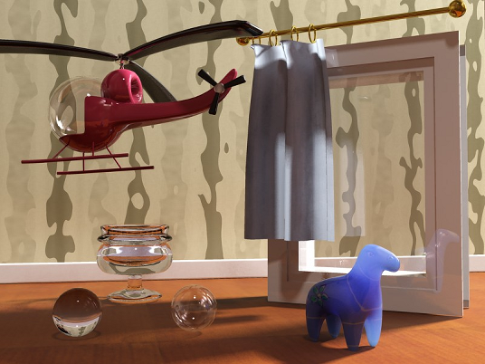
Solid versus thin-walled transparency and translucency
In the preceding illustration, the helicopter canopy, the window pane, the translucent curtain, and the right-hand sphere all use thin-walled transparency or translucency, whereas the glass goblet, the plastic horse, and the left-hand sphere all use solid transparency or translucency.
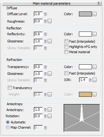
Diffuse Level controls the brightness of the diffuse color component. Range=0.0 to 1.0. Default=1.0.
Controls the diffuse color. The diffuse color is the color in direct light. Default=50% gray.
Click the map button to assign a Diffuse Color map. This button is a shortcut: You can also assign a Diffuse Color map on the General Maps rollout.
Roughness controls how quickly the diffuse component blends into the ambient component. Range=0.0 to 1.0. Default=0.0.
The diffuse component uses the Oren-Nayar shading model. When the Roughness value is 0.0, this is identical to classical Lambertian shading; but with higher values, the surface gets a more “powdery” look, as shown in the following illustration.
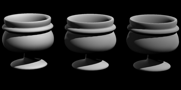
Left: Roughness=0.0
Center: 0.5
Right: 1.0
Click the map button to assign a Diffuse Roughness map. This button is a shortcut: You can also assign a Diffuse Roughness map on the General Maps rollout.
The overall level of reflectivity. Range=0.0 to 1.0. Default=0.6.
The Reflectivity and Color values combine to define the level of reflections as well as the intensity of the traditional highlight, also known as the specular highlight.
This value is the maximum value; the actual value also depends on the angle of the surface, and comes from the BRDF curve. This curve (see Interface) lets you define 0–degree reflectivity for surfaces facing the view and 90–degree reflectivity for surfaces perpendicular to the view.
Left: No reflectivity, with a purely diffuse material
Center: Angle-dependent reflectivity, with 0–degree reflectivity of 0.1 and a 90–degree reflectivity of 1.0
Right: Constant reflectivity, with both 0–degree reflectivity and 90–degree reflectivity of 0.9
The overall color of reflected light. Default=white.
Click the map button to assign a Reflection map. This button is a shortcut: You can also assign a Reflection map on the General Maps rollout.
Defines the surface “glossiness,” ranging from 1.0 (a perfect mirror) to 0.0 (a diffusely reflective surface). Default=1.0.
Left: Glossiness=1.0
Center: 0.5
Right: 0.25
Click the map button to assign a Glossiness map. This button is a shortcut: You can also assign a Glossiness map on the General Maps rollout.
The maximum number of samples (rays) that mental ray shoots to create glossy reflections. Higher values cause slow rendering but create a smoother result. Lower values render faster but create a grainier result. In general, 32 is enough for most renderings.
Available only when Glossiness does not equal 1.0. Because a Glossiness value of 1.0 creates a “perfect mirror,” it is meaningless to shoot multiple rays for this case, hence only one reflection ray is shot.
Glossy reflections need to trace multiple rays to yield a smooth result. This can affect performance. For this reason, the material includes the following two special features designed to enhance performance:
When on, a smoothing algorithm allows rays to be reused and smoothed. The result is faster and smoother glossy reflections at the expense of accuracy. Interpolation is explained in greater detail in Fast Glossy Interpolation Rollout.
When on, mental ray traces no actual reflection rays. Instead, only the highlights are shown, as well as soft reflections emulated with the help of using Final Gathering.
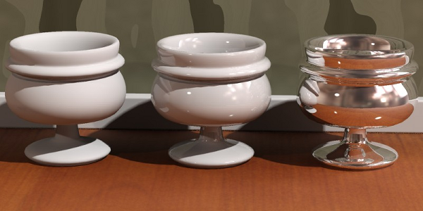
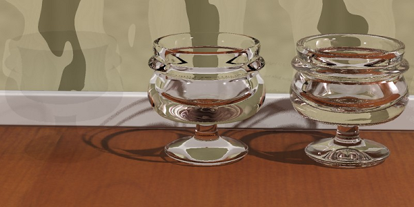
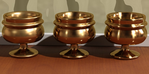
The Highlights+FG Only mode takes no additional rendering time compared to a non-glossy (diffuse) surface, yet can yield surprisingly convincing results. While it might not be completely convincing for “hero” objects in a scene, it can work very well for less-essential scene elements. It tends to work best on materials with weak reflections or extremely glossy (blurred) reflections, as shown in the following illustration:
The two cups on the left use real reflections, while those on the right use Highlights+FG Only.
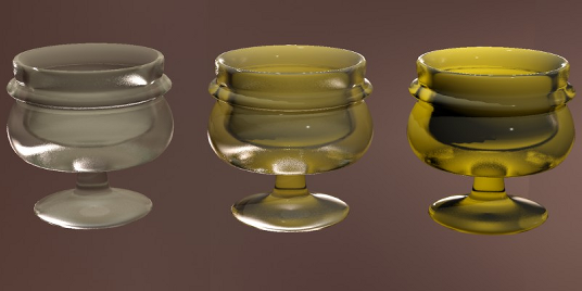
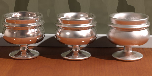
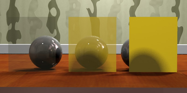
Metallic objects actually influence the color of their reflection, whereas other materials do not. For example, a gold bar will have gold-colored reflections, but a red glass orb does not have red reflections. This is supported through the Metal Material option:
Left: Non-metallic reflections (Metal Material is off). Reflections clearly contain the color of the objects they reflect and are not influenced by the color of the materials.
Center: Metallic reflections (Metal Material is on). Now the color of reflections are influenced by the color of the object.
Right: A variant of this with Reflectivity=0.5, creating a 50:50 mix between colored reflections and diffuse reflections
The color of refraction. While this color can be used to create “colored glass.” A slightly more accurate method to do this is described in the Colored Glass section of the Tips & Tricks topic.
Click the map button to assign a Refraction map. This button is a shortcut: You can also assign a Refraction map on the General Maps rollout.
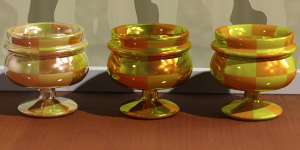
The sharpness of the refraction/transparency, ranging from 1.0 (completely clear transparency) to 0.0 (extremely diffuse or blurry transparency). Default=1.0.
Left: Refraction Glossiness=1.0
Center: Refraction Glossiness=0.5
Right: Refraction Glossiness=0.25
Glossy refraction needs to trace multiple rays to yield a smooth result. This can affect performance. For this reason, the material includes the following special feature designed to enhance performance:
When on, a smoothing algorithm allows rays to be reused and smoothed. The result is faster and smoother glossy refraction at the expense of accuracy. Interpolation is explained in greater detail in Fast Glossy Interpolation Rollout.
The maximum number of samples (rays) that mental ray shoots to create glossy refraction. Higher values cause slow rendering but create a smoother result. Lower values render faster but create a grainier result, like frosted glass. In general, 32 is enough for most renderings.
Available only when Glossiness does not equal 1.0. Because a Glossiness value of 1.0 creates a perfectly clear (non-blurry) transparency, it is meaningless to shoot multiple rays for this case; hence, only one refraction ray is shot.
The Index of Refraction, which is a measurement of how much a ray of light bends when entering a material.
The direction in which light bends depends on whether it is entering or exiting the object. The Arch & Design material use the direction of the surface normal as the primary cue for figuring out whether it is entering or exiting. It is therefore important to model transparent, refractive objects with the surface normals pointing in the proper direction.
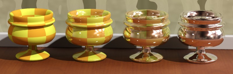
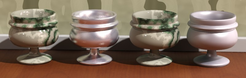
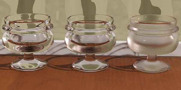
The IOR can also be used to define the BRDF curve, which is what happens in the class of transparent materials known as “dielectric” materials, and is illustrated here:
Left: IOR=1.0
Center: IOR=1.2
Right: IOR=1.5
The leftmost cup looks completely unrealistic, and is almost invisible. Because an IOR of 1.0, which equals that of air, is impossible in solid matter, we get no change in reflectivity across the material and hence perceive no edges or changes of any kind. On the other hand, the center and rightmost cups have realistic changes in reflectivity guided by the IOR.
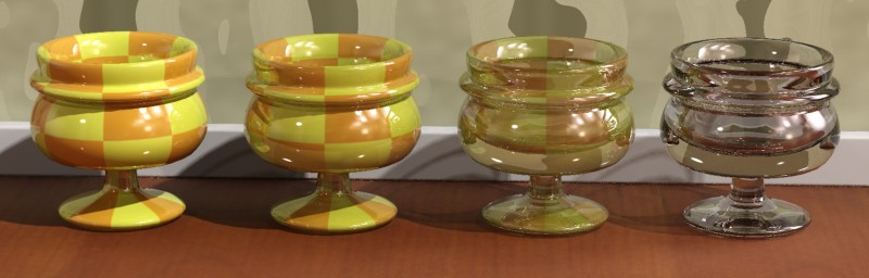
Instead of basing the reflectivity on the IOR, you can instead use the BRDF mode to set it manually:
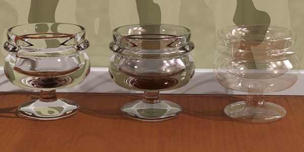
Different types of transparency
In the previous illustration, the leftmost cup acquires its curve from the index of refraction. The center cup has a manually defined curve, which has been set to a 90-degree reflectivity of 1.0 and a 0 degree reflectivity of 0.2; this looks a bit more like metallized glass. The rightmost cup uses the same BRDF curve, but instead is set to thin-walled transparency. Clearly, this method is better for making non-refractive objects than simply setting IOR to 1.0, as we tried in the left-hand example of the illustration before this one.
Translucency is handled as a special case of transparency; in order to use translucency, there must first exist some level of transparency. The implementation of translucency in the Arch & Design material is a simplification concerned solely with the transport of light from the back of an object to its front faces; it is not a true SSS (subsurface scattering) effect. You can create an SSS-like effect by using glossy transparency coupled with translucency, but this is neither as fast nor as powerful as the dedicated SSS shaders.
Determines how much of the existing transparency is used as translucency. For example, if Weight=0.0, all of the transparency is used as transparency. If Weight=0.3, 30 percent of the transparency is used as translucency.
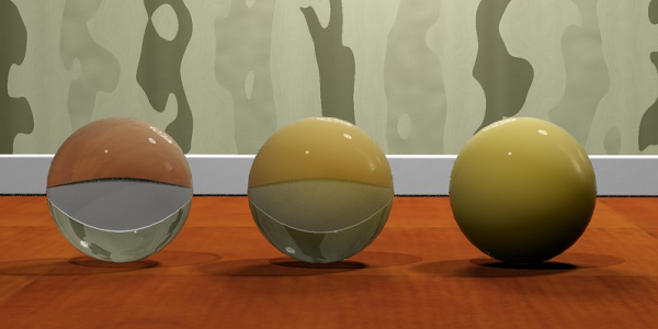
All: Transparency=0.75
Left: Weight=0.0
Center: Weight=0.5
Right: Weight=1.0
Translucency is intended for use primarily in thin-walled mode (as in the example above), to model things like curtains, rice paper, and similar effects. In thin-walled mode it simply allows the shading of the reverse side of the object to bleed through. The shader also operates in solid mode, but, as explained above, the SSS shaders are better suited for such purposes.
Solid translucency with:
Left: Weight=0.0
Center: Weight=0.5
Right: Weight=1.0
Click the map button to assign a Filter Color map. This button is a shortcut: You can also assign a Filter Color (Translucency) map on the General Maps rollout.
Controls the shape of the highlight. At 1.0, the highlight is round: That is, there is no anisotropy. At 0.01, the highlight is elongated. One axis of the highlight graph changes to show changes in this parameter. Default=1.0.
Left: Anisotropy=1.0
Center: Anisotropy=4.0
Right: Anisotropy=8.0
Click the map button to assign an Anisotropy map. This button is a shortcut: You can also assign an Anisotropy map on the General Maps rollout.
Changes the orientation of the highlight. The sample slot shows changes in orientation. This value can range from 0.0 to 1.0, with 1.0=360 degrees. So, for example, 0.25=90 degrees and 0.5=180 degrees. Default=0.0.

Left: Anisotropy Rotation=0.0
Center: Anisotropy Rotation=0.25
Right: Anisotropy Rotation=[texture map]
Click the map button to assign an Orientation (Anisotropy Rotation) map. This button is a shortcut: You can also assign an Orientation (Anisotropy Rotation) map on the General Maps rollout.
Lets you optionally apply anisotropy to a specific map channel.
When set to Automatic, the base rotation follows the object’s local coordinate system. Alternatively, if you choose Map Channel and set a channel number, the space that defines the stretch directions of the highlights is derived from the specified map channel’s texture space.
Also see Brushed Metal.


 Material Editor