 Command entry:
 Material Editor
  Standard material Maps rollout Anisotropy button (appears only for the Anisotropic or Multi-Layer shaders)
Command entry: Material Editor Arch & Design material General Maps rollout Surface Property Maps group Anisotropy button
Standard material Maps rollout Anisotropy button (appears only for the Anisotropic or Multi-Layer shaders)
Command entry: Material Editor Arch & Design material General Maps rollout Surface Property Maps group Anisotropy button
You can use a bitmap file or procedural map to control the Anisotropy parameter. The map controls the shape of the anisotropic highlight, roughly (but not necessarily) within the area specified by the Glossiness parameter. Black and white values have little effect. Maps with a good deal of grayscale values, such as Noise or Falloff, can be very effective.
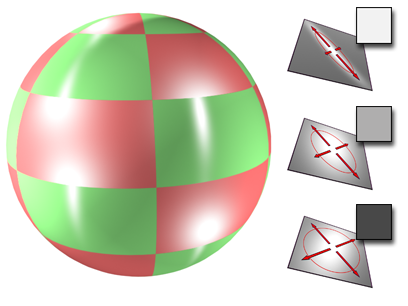
Using an Anisotropy map. The degree of stretching in the highlight depends on the level of gray in the map.
The effect of using an Anisotropy map is not very apparent unless Specular Level is fairly high and Glossiness is fairly low.
Reducing the Amount value of the Anisotropy map on the Maps rollout reduces the map's effect, thus increasing the effect of the Anisotropy value on the Basic Parameters rollout. When Amount is 0 percent, the map isn't used at all.
3ds Max opens the Material/Map Browser.
(If you choose Bitmap as the map type, 3ds Max opens a file dialog that lets you choose the image file.)
Alternatively, you can use the Slate Material Editor to wire a map node to the Anisotropy component.


