When Figure mode is active, the Structure rollout becomes available. This rollout includes parameters for changing the biped’s skeletal structure to match your character mesh (dinosaur, robot, human, and so on). You can also add up to three props to represent tools or weapons.
After setting parameters to suit your character, use the Height parameter to scale the biped to the size of the mesh representing your character. This is the first step in fitting a biped to a mesh in Figure mode.
To scale a biped and character mesh together:
 Select the biped, turn on
  (Figure Mode), and then change the biped Height setting on the Structure rollout.
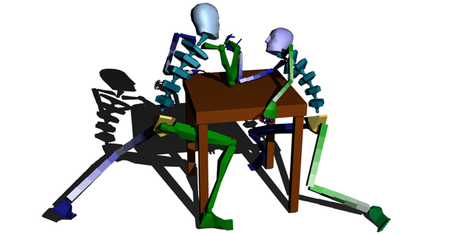
To skin a Biped with Twist Links:
This procedure takes into account the process of skinning a character and expands on the concept of using twist links to better deform a skinned mesh.

 Position a biped within the mesh.
Select the biped and turn on (Figure Mode).
Position a biped within the mesh.
Select the biped and turn on (Figure Mode).
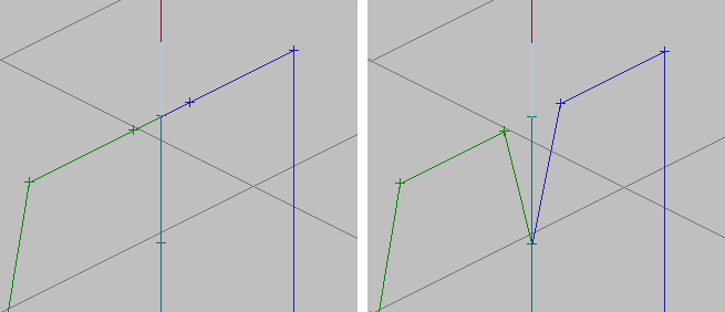
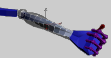
Both forearms have five twist links.
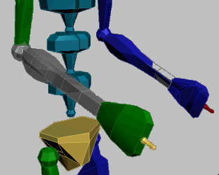
See-Through turned on for the right forearm only.
 Motion panel
  Parameters rollout, add all the biped bones to the skin except the forearms.
Select and freeze the twist bones again.
Parameters rollout, add all the biped bones to the skin except the forearms.
Select and freeze the twist bones again.
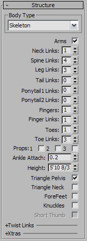
The drop-down list in the Body Type group lets you choose the biped's overall look:
The number of ponytail links. Default=0. Range=0 to 25.
You can animate hair with ponytail links. Ponytails are linked to a character’s head and can be used to animate other appendages. Reposition ponytails in Figure mode and use them to animate a character’s jaw, ears, nose, or anything that should move with the head.
Unlike the process of selecting the biped hand and dragging to reposition the entire arm, ponytails must be keyed using rotational transformations.
Enables up to three props, which can be used to represent tools or weapons attached to the biped. By default, prop 1 appears next to the right hand, prop 2 appears next to the left hand, and prop 3 appears centered between in front of the torso.
You can use animation controllers to animate props and can then collapse animation onto the prop’s transform controller for use in Mixer, Motion Flow, and Layer editing. For more information, see Using Props.
The ankles’ point of attachment along the corresponding foot block. The ankles can be placed anywhere along the centerline of the foot block, from the heel to the toe.
A value of 0 places the ankle attachment point at the heel. A value of 1 places the ankle attachment point at the toes. Range=0 to 1.
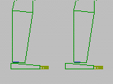
Left: Ankle Attach=0.25
Right: Ankle Attach=0.5
When on, creates links from the upper legs to the lowest biped spine object when Physique is attached. Normally the legs are linked to the biped pelvis object.
The pelvis area can be a problem when the mesh is deformed with Physique. Triangle Pelvis creates a more natural spline for mesh deformation.
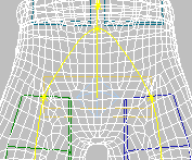
Triangle Pelvis
When on, links clavicles to the top spine link instead of to the neck. Default=off.
Like Triangle Pelvis, this feature has no effect on how the biped animates. It is a convenience when you skin the biped using Skin or Physique. Some meshes deform more naturally with the triangular neck configuration. If you have a mesh where this is the case, turn on Triangle Neck before you apply Skin or Physique.
Left: A normal neck. The neck is the parent of each clavicle.
Right: Triangle Neck. The top segment of the spine (Spine3) is the parent of each clavicle.
When on, the biped hands and fingers behave as feet and toes: When you set Planted keys for a hand, rotating the hand does not affect the position of the fingers. Default=off.
This option turns the biped into a quadruped. You can think of the name of this option as also meaning “Four Feet.”
As with feet, the planted behavior applies only to IK periods of biped animation. After you set a Free key, the fingers rotate as children of the hands, using FK, until you set another Planted key.
This option is disabled when Knuckles (see following) is on.
When on, uses an anatomically correct hand structure, with bones for each digit. Default=off.
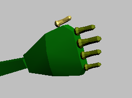
A standard biped hand. This setup doesn’t allow for finely detailed hand animation.
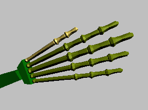
A biped hand with Knuckles enabled. The hand has a small base and individual bones for all its digits, allowing for detailed animation.
When you turn on Knuckles, 3ds Max automatically sets the Fingers value to 5 and Finger Links to 4. Depending on the character you are animating, you can reduce the value of Fingers or Finger Links. Knuckles supports zero to five fingers on each hand, and from one to four finger links.
This option is disabled when ForeFeet is on.
You might want to turn off Short Thumb when you are creating a nonhuman character.
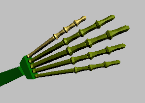
Short Thumb turned off while Finger Links=4, so that all digits have four bones.
The bone twist option includes all limbs. These settings allow better mesh deformation on skinned models (using Physique or Skin) when twisting occurs on animated limbs. Use the Twist Poses rollout for better control over your twist links.
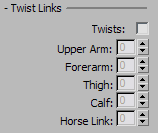
Enables twist links for biped limbs. When enabled, twist links become visible but remain frozen. You can unfreeze them using Unfreeze By Name or Unfreeze By Hit on the Freeze rollout.
Sets the number of twist links in the horse link: the additional, lower leg bone that appears when you set Leg Links to 4. Default=0. Range=0 to 10.
The Xtras group lets you add extra tails to the biped. Extra tails are like ponytails: they don’t use inverse kinematics, and you must animate them with forward kinematics such as rotation keys. On the other hand, extra tails don’t have to be attached to the head.
Animation for extra tails is saved in MAX and BIP files.
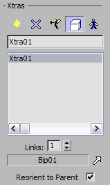


 Create Xtra
 Delete Xtra
 Create Opposite Xtra
 Synch Selection
 Select Symmetrical
 Pick Parent