The Skin modifier is a skeletal deformation tool that lets you deform one object with another object. Mesh, patch, or NURBS objects can be deformed by bones, splines, and other objects.
Applying the Skin modifier and then assigning bones gives each bone a capsule-shaped "envelope." Vertices of the modified object within these envelopes move with the bones. Where envelopes overlap, vertex motion is a blend between the envelopes.
By default, each vertex that's affected by a single bone is given a weight value of 1.0, which means it's affected by that bone only. Vertices within the intersection of two bones' envelopes have two weight values: one for each bone. And you can use Skin modifier toolsets such as the Weight Tool dialog to arbitrarily assign vertices to any number of bones. The ratio of a vertex's weight values, which always total 1.0, determine the relative extent to which each bone's motion affects the vertex. For example, if a vertex's weight with respect to bone 1 is 0.8 and its weight with respect to bone 2 is 0.2, then the motion of bone 1 will have four times greater influence on the vertex than will the motion of bone 2.
The initial envelope shape and position depends on the type of bone object. Bones create a linear envelope that extends along the longest axis of the bone geometry. Spline objects create envelopes that follow the curve of the spline. Primitive objects create an envelope that follows the longest axis of the object.
You can also deform the mesh based on the angle of the bones. Three deformers let you shape the mesh based on bone angles:
You can apply the Skin modifier to several objects at the same time.
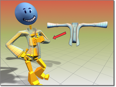
Jacket object deformed using the Skin modifier
In 3ds Max you can mirror envelope and vertex assignments from one side of the mesh to the other with commands on the Mirror Parameters rollout.
 place the skeleton inside the mesh or patch object so that its elements are able to influence polygons or patches in their
immediate vicinity.
place the skeleton inside the mesh or patch object so that its elements are able to influence polygons or patches in their
immediate vicinity.
 Select the mesh or patch object and apply the Skin modifier.
Each selected vertex is surrounded by a small white rectangle.
To mirror envelope or vertex weight settings:
The mirror plane appears at the position and orientation of the mesh's pivot point.
To adjust the skin and/or bones without affecting the envelopes:
 Save the scene.
This is a potentially destructive operation, so it's best not to take any chances with your data.
Select the object to which the Skin modifier is applied.
To adjust the bones only, you can also use skin pose.
Example: To apply the Skin modifier to a cylinder with a bones skeleton:
 Create panel, with
  (Geometry) active, under Standard Primitives, click Cylinder.
Create panel, click
(Geometry) active, under Standard Primitives, click Cylinder.
Create panel, click  (Systems). On the Object Type rollout, click Bones.
Make sure an IK Solver is chosen in the IK Solver list. Turn on Assign To Children. (This should turn on Assign To Root as well.)
Three bones display. Two of them are within the middle of the cylinder.
Select the cylinder.
 Modify panel
  Modifier List, choose Skin.
select the bone end effector (IK Chain01) and move it around.
Modifier List, choose Skin.
select the bone end effector (IK Chain01) and move it around.
The cylinder deforms to follow the bones. To adjust envelopes to refine the surface deformation, choose the Skin modifier's Envelope sub-object level, and use the Edit Envelopes controls to resize envelopes and change vertex weights.
Example: To use a morph angle deformer:
Create the cylinder and bones from the preceding procedure before you continue with this procedure.
region-select a good portion of the vertices that are controlled by both bones.
The Deformer Parameters rollout displays. A base morph target is the first and only target in the list.
There is a doubling effect of the morph if you don’t delete or deactivate the Edit Mesh modifier.
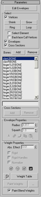
The Skin Modifier interface includes the following rollouts:
A number of Skin modifier commands are also available from the quad menu on the Tools 1 and Tools 2 quadrants:
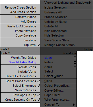
The following filtering options are grouped together to help you work on a particular task, by preventing you from accidentally selecting the wrong item in the viewports.
 You can rotate around selected vertices using Orbit SubObject on the Orbit flyout. You can also rotate around a selected envelope as long as no vertices are selected, as they have precedence.
 You can zoom on selected vertices using Zoom Extents Selected from the Zoom Extents flyout. You can also zoom on an envelope if no vertices are selected.
The first step, after applying the Skin modifier to an object, is to determine which bones participate in the object's weighting. Every bone you choose influences the weighted object with its envelope, which you can configure in the Envelope Properties group.
Lists all bones in the system. Highlighting a bone in the list displays that bone's envelope and the vertices influenced by the envelope.
An horizontal scroll bar appears if a bone's name is longer than the window's width.
Example: $'Sphere01'.modifiers[#Skin].shortenBoneNames = false
For detailed information about the MAXScript utility, see the MAXScript Help, available from Help menu MAXScript Help.
Enter a bone name to highlight it in the bone list above. The highlighting goes to the first matching bone.
Use these methods for finding bone names faster:
By default, each envelope has two round, lateral cross sections, one at each end of the envelope. These options add and remove cross sections from envelopes.

A squash multiplier for bones that stretch. This is a single value that reduces or increases the amount of squash applied to a bone when it is stretched with Freeze Length off, and Squash on.
This toggle determines how vertex weights are calculated for vertices between inner and outer envelopes.
 AbsoluteA vertex must merely fall inside the brown outer envelope to have 100% assignment weight to that particular bone. A vertex
falling inside more than one outer envelope will be assigned multiple weights summing to 100% based on where it falls in the
gradients of each envelope.
AbsoluteA vertex must merely fall inside the brown outer envelope to have 100% assignment weight to that particular bone. A vertex
falling inside more than one outer envelope will be assigned multiple weights summing to 100% based on where it falls in the
gradients of each envelope.
 RelativeA vertex falling only within an outer envelope will not receive 100% weighting. A vertex must either fall inside two or more
outer envelopes whose gradients sum to 100% or greater or the vertex must fall within a red inner envelope to have 100% weight.
Any points within a red inner envelope will be 100% locked to that bone. Vertices falling within multiple inner envelopes
will receive weighting distributed over those bones.
RelativeA vertex falling only within an outer envelope will not receive 100% weighting. A vertex must either fall inside two or more
outer envelopes whose gradients sum to 100% or greater or the vertex must fall within a red inner envelope to have 100% weight.
Any points within a red inner envelope will be 100% locked to that bone. Vertices falling within multiple inner envelopes
will receive weighting distributed over those bones.

 Envelope Visibility
Choose a falloff curve for the displayed envelopes.
Weight falls off in the area between the inner and outer envelope boundaries if envelopes overlap and Absolute is turned on. This setting lets you specify how the falloff is handled:
 Falloff Fast OutWeight falls off quickly.
 Falloff Slow OutWeight falls off slowly.
 Falloff LinearWeight falls off in a linear way.
 Falloff SinualWeight falls off in a sinusoidal way.
 Copy
CopyCopies the currently selected envelope size and shape to memory. Turn on sub-object Envelopes, choose one bone in the list, click Copy, then choose another bone in the list and click Paste to copy an envelope from one bone to another.
Paste commands are on a flyout with the following options:
 PastePastes the copy buffer to the current selected bone.
 Paste to All BonesPastes the copy buffer to all bones in the modifier.
 Paste to Multiple BonesPastes the copy buffer to selected bones. A dialog allows you to choose the bones to paste to.
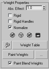
Enter an absolute weight for the selected bone to selected vertices.
Choose the Envelope sub-object level, turn on Vertices in the Parameters rollout Select group, select a vertex or vertices, and then use the Abs. Effect spinner to assign weight. Selected vertices move
in the viewports as their weight changes.
 Exclude Selected Verts
 Include Selected Verts
 Select Excluded Verts
Click to bake the current vertex weights. Baked weights are not affected by envelope changes, only by changes to Abs. Effect or weights in the Weight Table.
 Weight Tool
Displays the Weight Tool dialog, which offers control tools to help you assign and blend weights on selected vertices.
Displays a table for viewing and changing weights for all bones in the skeletal structure. See Weight Table.
Click and drag the cursor over vertices in the viewports to brush on weights for the selected bone.
 Painter Options [ellipsis]
Opens the Painter Options dialog, where you can set parameters for weight painting.
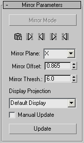
Activates Mirror mode, which lets you mirror the envelopes and vertex assignments from one side of the mesh to the other. This mode is available only at the Envelope sub-object level.
Mirror mode uses the Mirror Plane setting to determine the “left side” and “right side” of the mesh. When you turn on Mirror Mode, the vertices on the left side of the mirror plane turn blue, while the vertices on the right turn green. Vertices that are neither left nor right turn red, including vertices at the mirror plane. If vertices don't change color appropriately, you might have to increase the Mirror Thresh value to expand the range used to determine the left and right sides.
If you select vertices or bones, the selected vertices or bones turn yellow, and the corresponding match on the other side of the mesh turns a brighter blue or green. This can help you check for matches.
 Mirror Paste
 Paste Green to Blue Bones
 Paste Blue to Green Bones
 Paste Green to Blue Verts
 Paste Blue to Green Verts
Determines the plane that will be used to determine the left and right sides. The plane appears in the viewport at the mesh's pivot point when you turn on Mirror mode. The selected mesh's local axes are used as the basis for the plane. If several objects are selected, one object's local axes are used. Default=X.
Sets the relative distance the mirroring tools will look when setting vertices as left or right. If some vertices in the mesh (other than those at the mirror plane) are not colored blue or green when you turn on Mirror mode, increase the Mirror Thresh value to include a larger area of the character. You can also increase this value to compensate for lack of symmetry in asymmetrical models.
When Display Projection is set to Default Display, selecting vertices on one side of the mirror plane automatically projects the selection to the opposite side. The Positive and Negative options allow selection of vertices on one side of the character only. The None option does not project selected vertices to either side. Default=Default Display.
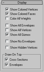
When on, hidden vertices are visible. Otherwise, they remain hidden until you enable the option or go into the object's modifier (Editable Mesh or Editable Poly), and then click Unhide All on the Selection rollout or Edit Geometry rollout, respectively. Default=off.
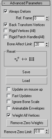
A toggle useful for editing the transformation relationship between bones and the controlled points. This relationship is initially set when Skin is applied. To change the relationship, turn off Always Deform, move the object or the bones, and reactivate. The new transformation relationship is now used.
Sets the frame where the bones and the mesh are in a reference position.
Normally this is frame 0. If frame 0 is the reference frame, start your animation at frame 1 or later . If you need to adjust bones relative to the mesh, move the time slider to frame 0, turn off Always Deform, move the bones into the correct position, and then turn on Always Deform.
Allows you to link the mesh to the bone structure. Ordinarily, when you do this, any movement of the bones causes the mesh to move twice as far as it should, because it moves once with the bones and once with the link. Enabling this option prevents the mesh from moving twice under these circumstances.
When on, effectively assigns each vertex to the bone whose envelope has the most influence, as though weighted 100% to that bone. Vertices will not have weight distributed over more than one bone and the deformation of the skinned object is rigid. This is mainly used with game engines that do not support weighted point transformation.
Allows you to save and load the envelope position and shape, as well as the vertex weights. If you load a saved file onto a different system of bones, you can use the Load Envelopes dialog to match the incoming bones to the current bones.
Turn this option on to leave a skinned mesh unaffected by a scaled bone. Default=off.
When on, forces all vertices that are not under the control of an envelope to be weighted to the bone closest to them. Has no effect on vertices that are manually weighted. Default=on.
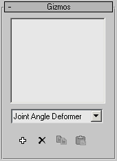
Controls in the Gizmos rollout allow you to deform the mesh according to the angle of the joint, and to add gizmos to selected points on the object. The rollout consists of a list box containing all the gizmos for this modifier, a drop-down list of the current types of gizmos, and four buttons (Add, Remove, Copy, and Paste).
The workflow for adding a gizmo is to select the vertices that you want to affect, select the bones that will drive the deformation, and then click the Add button.
There are three deformers available:
Keep these distinctions in mind when you select vertices to deform. For example, if you want to use the Joint Angle deformer, then select vertices close to the joint that will drive the deformation. If you want the parent bone vertices to deform like a biceps muscle, then select vertices that are only assigned to the parent bone before adding the Bulge Angle deformer. If all the vertices of the parent and child bone must deform, then select all of the vertices and add the Morph Angle deformer.
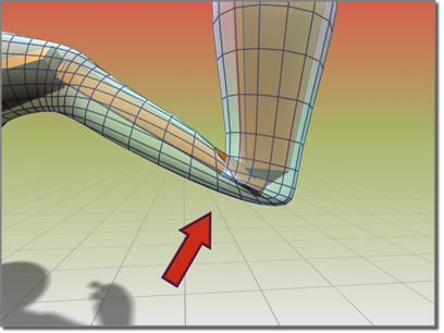
Bending the arm without the Morph Angle deformer causes the sleeve to crumple.
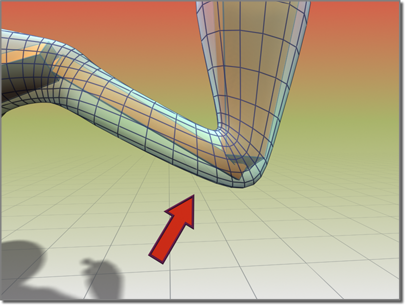
Using the Morph Angle deformer creates a smooth bend in the sleeve.
 Add Gizmo
Adds the current Gizmo to the selected vertices.
To add a gizmo, first select the child bone for the joint to deform, then select the vertices to deform. You can then add a gizmo.
After you add or highlight a gizmo, a Deformer Parameters or Gizmo Parameters rollout opens with gizmo parameters that you can adjust (see following).
 Remove Gizmo
 Copy Gizmo
Deformer Parameters rollout (Morph Angle deformer)
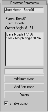
These parameters apply to the Morph Angle deformer. One way to create morph targets, after the morph gizmo is added, is to add an Edit Mesh modifier to the stack above the Skin modifier. Use the vertex controls in the Edit Mesh modifier to shape the geometry. Then go back in the stack to the Skin modifier and click Add From Stack. You can then delete the Edit Mesh modifier. Add From Stack looks at the last modifier in the stack to get the morph target. Note that when you go back down to the Skin modifier, the morph effect is doubled; you can rectify this by deleting or deactivating the Edit Mesh modifier.
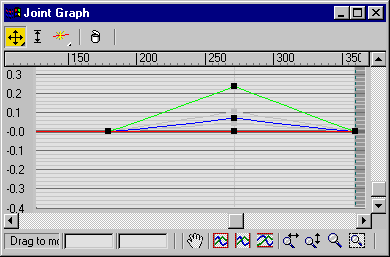
Gizmo/Deformer parameters rollout (Joint Angle and Bulge Angle deformers)
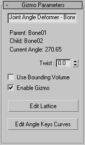
These parameters apply to the Joint Angle and Bulge Angle deformers,which operate in similar ways. The difference is that the Bulge Angle deformer works only on vertices of the parent bone, while the Joint Angle deformer works on vertices of both the child and parent bones.
To apply either of these deformers, first select the child link, then select vertices on the mesh, and then apply the deformer.
Remember to turn on Vertices in the Parameters rollout Select group before region-selecting vertices in the viewports.
Once the deformer is applied, turn on Edit Lattice and move the lattice control points in the viewports to deform the mesh at different bone angles.
The Load Envelopes dialog associated with the Skin modifier allows you to load saved envelopes to specific bones. This resizable dialog shows the current envelopes in your scene and the incoming envelopes. Use the controls to manipulate the incoming envelopes so they align with the current envelopes.
This dialog is launched from the Skin modifier and provides tools to select vertices and assign them weights. You can also copy, paste, and blend weights between vertices. Each vertex you select displays the objects contributing to its weighting in the dialog list.
The weight table for the Skin modifier is used to change vertex weights for several vertices and bones at a time. This table appears when you click the Weight Table button.