These tools are for navigating and editing biped keys.
Tools in the Key Info rollout allow you to do the following:
When the Body Vertical COM (center of mass) track is active, you can change the vertical dynamics of the motion, on a key-by-key basis. When the Body Horizontal COM track is active you can change the balance factor for shifts in weight distribution.
Groups of the Key Info rollout are unavailable depending on what part of the biped is selected and if a key is current. Body Vertical, Body Horizontal, and Body Rotation refer to the three tracks used to animate the biped center of mass. Select one of the three center of mass tracks on the Track Selection rollout, then use Next Key or Previous Key to find a key to edit.
The Key Info rollout is divided up into several groups: TCB, IK, Head, Body, and Prop. You can expand and hide each of these groups by clicking the line next to its name.
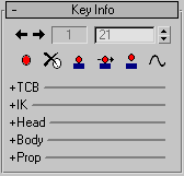
 Next Key-Previous Key
 Set Key
Creates keys at the current frame when you are moving biped objects. This is identical to Set Key on the 3ds Max toolbar.
You can experiment with different biped poses without updating the motion until you find the desired pose. You can also quickly fine tune your motion by setting a key and adjusting the key parameters on the Key Info rollout without having to transform the biped in the viewports.
 Delete Key
Deletes the key of the selected object at the current frame.
By default, biped arm, hand, and finger keys are stored in the clavicle track. If you delete keys for any one of these objects, you lose positions for the rest of the arm objects at that frame. If you plan on extensive hand animation, turn on Arms in the Separate Tracks group of the Keyframing Tools rollout. This creates separate tracks for each biped arm object. Deleting an upper arm key will preserve hand and finger keys.
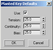
 Set Planted Key
Sets a biped key with IK Blend=1, Join To Previous IK Key turned on, and Object selected in the IK group.
In a Footstep or Freefrom animation, all footsteps that do not slide should have Join To Previous IK Key turned on.
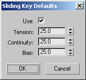
 Set Sliding Key
Sets a biped key with IK Blend=1, Join To Previous IK Key turned off, and Object selected in the IK group. This creates a sliding footstep. Sliding footsteps display in the viewports with a line running through the middle of the footstep. Sliding footsteps are understood as footsteps with moving IK constraints.
In a Footstep or Freeform animation, if the foot slides rather than being planted, use Set Sliding Key.
For a discussion of walk-cycle animation that covers the user of Planted Key, see Sliding Key Defaults dialog.
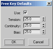
 Set Free Key
Sets a biped key with IK Blend=0, Join To Previous IK Key turned off, and Body selected in the IK group.
In a Footstep or Freeform animation, a biped leg in a move state should have a “free” key.
To change the default values for TCB keys, right-click either Set Planted Key, Set Sliding Key, or Set Free Key to open the respective dialog.
 Trajectories
Shows and hides trajectories for the selected biped object. You can edit keys on the biped's horizontal and vertical track by turning on Trajectories, turning on Sub-Object, selecting the horizontal or vertical center of mass track, and transforming keys in the viewports.
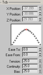
You can use the TCB controls to adjust easing and trajectories on keys that already exist.
Charts the effect that changing the controller properties will have on the animation. The red mark at the top of the curve represents the key. The marks to the left and right of the curve represent an even division of time to either side of the key.
The TCB graph is a stylized representation of the animation around a single key.
Controls the amount of curvature in the animation curve.
High Tension produces a linear curve. It also has a slight Ease To and Ease From effect.
Low Tension produces a very wide, rounded, curve. It also has a slight negative Ease To and Ease From effect.
The default value of 25 produces an even amount of curvature through the key.
Controls the tangential property of the curve at the key. The default setting is the only value that produces a smooth animation curve through the key. All other values produce a discontinuity in the animation curve causing an abrupt change in the animation. Default=25.
High Continuity values create curved overshoot on both sides of the key.
Low Continuity values create a linear animation curve. Low continuity creates a linear curve similar to high tension except without the Ease To and Ease From side effect.
The default setting creates a smooth continuous curve at the key.
Controls where the animation curve occurs with respect to the key. Default=25.
High Bias pushes the curve beyond the key. This produces a linear curve coming into the key and an exaggerated curve leaving the key.
Low Bias pulls the curve before the key. This produces an exaggerated curve coming into the key and a linear curve leaving the key.
The default setting distributes the curve evenly to both sides of the key.
This group lets you set IK keys and adjust parameters for IK keys.

Determines how character studio mixes forward kinematics and inverse kinematics to interpolate an intermediate position. An example of forward kinematics is moving the arm to control the hand. An example of inverse kinematics is moving the hand to control the arm.
Activates when a biped arm or leg (hand and foot) key is current.
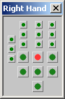
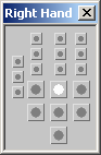
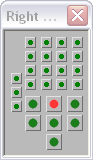
 Pivot Selection Dialog
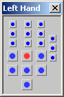
Opens a small dialog that shows the current pivot for the selected limb on the limb's respective hand or foot, and lets you change it. When the chart is green (or blue) and red, indicating that you're on an IK key, the red dot indicates the current location of the pivot. To designate a different pivot, click another dot on the chart. This provides an alternative method to using Select Pivot (see preceding).
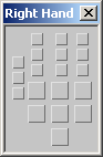
The dialog is named according to the displayed hand or foot, depicts the actual number of digits and joints in use, and resizes itself accordingly. The displayed chart uses three different schemes, depending on the context:
These are shown in the following illustration:
When you have turned on Knuckles, the hand chart shows all bones; for example:
 Select IK Object
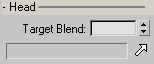
The Head group lets you define a target object for the target to look at.
Determines the extent to which the target blends with the head's existing animation.
A setting of 1.0 causes the head to look directly at the target, 0.5 causes the head to blend half of its existing animation with looking at the target, and a setting of 0.0 causes the head to ignore the target, maintaining its existing animation.
Select Look At Target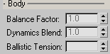
These parameters apply to the biped center of mass and are used by character studio to calculate the biped’s airborne trajectory based on gravity (GravAccel) and time between footsteps, the amount of knee bend on landing (Ballistic Tension) and how the biped objects adapt to maintain balance (Balance Factor).
Positions the biped's weight anywhere along a line that extends from the center of mass to the biped’s head. This center of mass (Body Horizontal track) parameter can be keyframed. To activate Balance Factor select the Horizontal Track (in the Track Selection rollout), set a key and enter a value in the Balance Factor field.
For example, to create a sit then walk sequence, you could shift the biped’s weight (balance) between 0 (the character is supported by the chair) for the sit key and 1 for the stand key (the character’s pelvis shifts to maintain balance).
If a character is seated, and reaches across the table, leave Balance Factor at 0; however the character leans, he will pivot from the center of mass. The pelvis will not move back to maintain balance.
In a walking motion, a value of 2 will swing the hips and keep the biped head steady; a value of 0 will keep the hips steady and swing the upper body.
A Balance Factor value of 0 in the first image causes the biped not to compensate for weight.
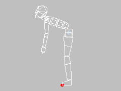
A Balance Factor value of 2 in the second image causes the biped pelvis to move away from the Center of Mass to compensate for weight.
The Balance Factor determines how far the biped's hips will shift forward or backward to compensate for forward or backward bending of the spine. When the biped has a normal weight distribution between the upper and lower body, the default value of 1 causes the hips to swing backward as the biped bends over to compensate for the forward weight.
At times, when the biped leans, you will want the biped's hips to refrain from shifting to compensate for the forward weight. This would be when the biped is sitting or falling down. A Balance Factor of 0 (the minimum value) causes the hips to stay still when the biped leans forward or backward.
A value of 0 places the biped’s weight at the center of mass. A value of 1 places the biped’s weight above the center of mass. A value of 2 places the biped’s weight in the head. Click the spinner up arrow to move the biped’s weight distribution toward the head. Range=0.0 to 2.0; Default=1.
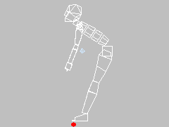
Select the Body Vertical track (center of mass vertical track) and control the amount of gravity in an airborne period, as in a running or jumping motion. This parameter has no effect on a walking motion where footsteps overlap.
The vertical center of mass track Dynamics Blend parameter is set to 1 for both keys (white squares) in the first jump, and to .5 in the second jump.
A value of 1 uses the GravAccel value to calculate gravity. A value of 0 removes the effects of gravity calculation and flattens a jumping or airborne motion.
Select the Body Vertical track (COM) and control the amount of spring or tension when the biped lands or takes off from a jump or run step. The change is subtle.
A walk cycle will not activate this value. The biped has to be airborne, then the Lift and Touch vertical keys will display a Ballistic Tension value.
If there are more than three vertical keys during a support period, you can also edit Ballistic Tension for the lift-off key; otherwise Biped uses the same value for touchdown and lift-off, since it is assumed that there is only one vertical dip in the motion. Low values are high tension (less dip in the trajectory). Default=0.5; Range=0 to 1;


 Motion panel