Chapter 24, Expressions
| Removing an Expression | Expression Reference Tables | ||
Chapter 24, Expressions |
|||
 Example: Using Linked Attributes to Drive Animation
Example: Using Functions to Drive Animation
Example: Animating Layers in Reaction
The following examples will show you some of the ways expressions can be used to save time in building your animations. You can create an expression for one channel and use the same expression for other channels so that the other channels automatically behave in relation to the first one.

This example consists of a simple animation where the Photo Lab red channel Gain attribute drives the Radial Ramp tool's Y Center attribute--see Setting Keys Manually, Radial Ramp Tool, and Processing Images with Photo Lab.
Note: It is assumed that you currently have Player, Schematic, and Composition Browser open. With the focus on Schematic, use Ctrl + N to create a new composition.
From the Tools tab, drag the Radial Ramp tool from the Image Generation folder to the dependency graph in the Schematic view.
Drag the Photo Lab tool from the Color Correction folder to Schematic and place it after the Radial Ramp tool.
The dependency graph should look like this.
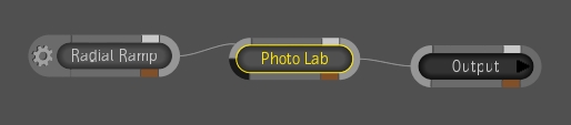
 "Show full-size image")
In the Player controls, change the composition's total number of frames to 100.

 "Show full-size image")
In the Radial Ramp tool UI, modify the following attribute values with the following settings:
| Attribute | New Setting |
| Start Color Green (G) channel | 0.500 |
| X Radius | 30 |
| Y Radius | 16 |
| X Falloff | 85 |
| Y Falloff | 116 |
The Radial Ramp should look like this.
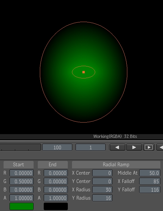
 "Show full-size image")
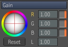
You can now set an expression for the Y Center attribute that enables it to be driven by the Photo Lab's Gain, Red channel attribute.
Right-click inside the Y Center value field. And select Set Expression.
 "Show full-size image")
The Expresso Calculator appears along with a dashed green line at the top of the Y Center value field. This indicates that an expression has been applied.
 "Show full-size image")
|
In the text field at the top of the calculator, type in the following expression string.

 "Show full-size image")
This string is typical of what an expression looks like. The Y Center of the Radial Ramp points to the red channel of the gain controls in the Photo Lab tool, and links them. If you are familiar with expressions, you can simply type the expression into the text field (using the correct syntax and order), but if you are not sure of the exact sequence or writing convention, you can cycle through the various expression tokens that make up the string by using Alt + backslash (/) on the keyboard.
Note: Both Alt keys work, but only the backslash (/) that is on the question mark (?) key can be used.
By opening a Composition Browser view, you can see the socket names of each tool attribute once the menus are expanded. You can use these names as a reference when creating expression strings, as this is how they should look in the expression.
 "Show full-size image")
Note: When cycling through and selecting a tool's attribute levels, you must separate each level with a period.
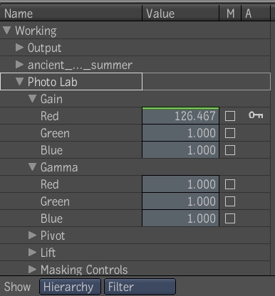
Open the Photo Lab tool UI.
Select Autokey.
Change the exposure units to Gain.
Mark the red (R) channel of the Gain for keyframing by clicking the R label--see Marking Attributes for Keyframing.
 "Show full-size image")
In intervals of 20 keyframes, increase the gain on the red channel, so that it is at its maximum by frame 100.
Play the animation.
This example shows you how pre-established functions can be used as expressions to drive animation--see Expression Reference Tables.
The goal of this example is to create random noise using the Noise tool--see Noise Tool. You could create the appearance of random noise by modifying the Noise Seed attribute using periodic keyframes. However, a more simple approach is to use a random number function. In this case, the TrueRand function is used.
Note: It is assumed that you currently have the Player, Schematic, and Composition Browser open. With the focus on Schematic, use Ctrl + N to create a new composition.
From the Tools tab, drag the Noise tool from the Image Generation folder to the dependency graph in the Schematic view and connect it to the Output node.
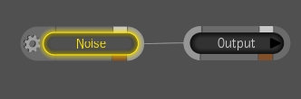
 "Show full-size image")
In the Player controls, change the composition's total number of frames to 100.
In the tool UI, set the Fill, Start, and End color preferences.
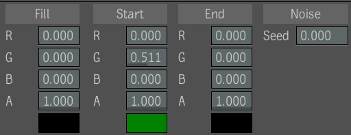
 "Show full-size image")
Right-click the Noise Seed value field and select Set Expression from the menu.
The Expresso Calculator appears along with a dashed green line at the top of the Noise Seed value field. This indicates that an expression is about to be applied, or has already been applied.
 "Show full-size image")
|
Select the Random button if it is not already selected.
Select the TrueRand button.
An empty expression appears in the text field.
Note: If you are familiar with the syntax of expressions, you can type them directly into the text field.
![]()
 "Show full-size image")
As the TrueRand function description indicates (see Random Number Functions) the function returns a truly random value between two given numbers. Since the Noise Seed value can range from 0 to 1, it is suggested that these values be used as the range.
Enter the value range of 0 to 1 between the brackets in the text field, making sure you separate the values with a comma.
Play the composition.
Note: You can view the expression in a graph view at any time by right-clicking the attribute's value field containing the expression, and then selecting Edit Expression from the menu. The Expresso Calculator appears. Select the Graph button to view the expression in a graph.
There are other expressions, and combinations of expressions that you can use to achieve the same results. For example, you can create random noise (with the Noise tool) by using the Rand function where the seed is calculated as time (t) multiplied (*) by the number of frames in the composition. Therefore, if the composition is 100 frames long, the expression would look like this:
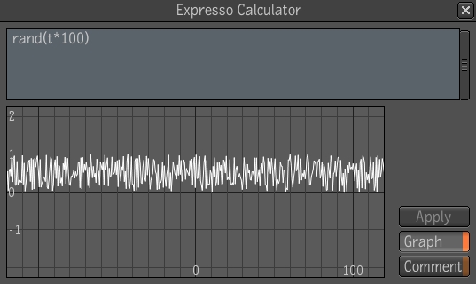
 "Show full-size image")
Another expression that can be used to create random noise with the Noise tool is the Abs math function.
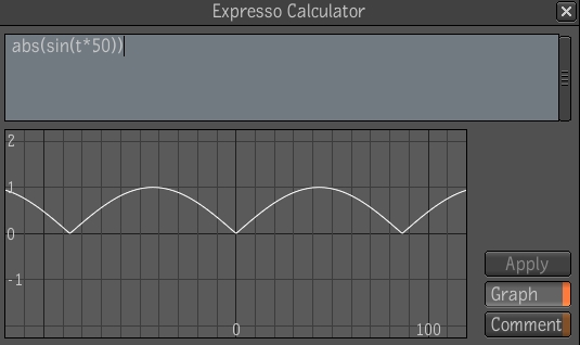
 "Show full-size image")
This expression indicates the Noise Seed is based on an absolute value (anything between 0 and 1) of the angle (in radians) of the sine wave created by the current time (t). It is then multiplied (*) by a frequency of 50. The expression would still be valid if the Abs math function were not part of the string.
This example is somewhat more involved in that it uses the Eval time function within a Reaction node--see Time Functions and Basic Compositing in Reaction.
This example has two parts. First you'll set up the display and then you'll create the animation.
Note: It is assumed that you currently have a Player, Schematic, and Composition Browser open. With the focus on Schematic, use Ctrl + N to create a new composition.
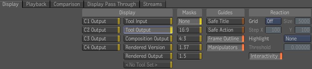
Before you begin, make sure that you set the Player display settings as follows.
Open the Gate UI and swipe south to display the Player options.
The Player control panel is displayed across the bottom of the screen. By default the Display tab is selected and you can immediately access the display settings and options.
 "Show full-size image")
Select Tool Output to view the results of the Reaction composition in the Player.
Under Guides, select Frame Outline.
Under Reaction, select Interactivity.
From the Tools tab, drag the Reaction tool to the dependency graph in the Schematic view, and connect it to the Output node.
Note: Usually, before you composite or add effects such as an animation in Reaction, you typically set the background. The background is the rendering plane for the composition and sets the format. If you connect a Reaction tool to an image or tool output in an existing dependency graph, the background is set automatically. You can change the background at any time.
Select the Reaction tab.
In the Player controls, change the composition's total number of frames to 100.
At the bottom of the Layer Editor, select Box and click Create.
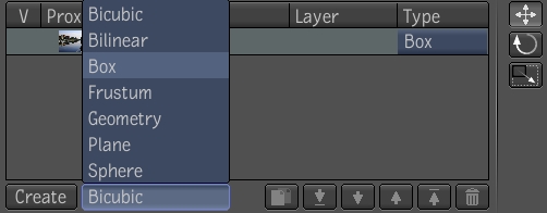
 "Show full-size image")
A new layer (a cube) is added to Reaction. Rename the layer by clicking in its text field and pressing F2. Type in the new name, Box1, and press Enter.
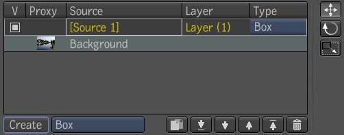
 "Show full-size image")
Depending on which preset you have chosen to view, the box you have created most likely takes up the entire Player view.
Select the Reaction tab.
 "Show full-size image")
|
Note: To help you create an appropriate view of the animation, you can modify the Player view by adjusting the zoom--see Zooming or Panning a View.
Use the Translate tool to move the box to the bottom-left corner of the view by grabbing the X or Y axis with the cursor. If you do not see the axes icon in the Player, go to the Player display options and select Tool Output under Display, and Icons under Guides.
Mark the X and Y Position attributes for keyframing.
Select Autokey.
Using the Translate tool, create a motion path with the cube in Autokey to the right-hand side of the Player view. Try to span all 100 frames.
Play the animation.
Select the Reaction tab and create a second box, Box2, layer by following steps 5 through 8.
Right-click in Box2's X Position attribute value field and select Set Expression.
The Expresso Calculator appears.
Insert the following expression.
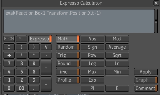
 "Show full-size image")
Repeat steps 12 and 13 for Box2's Y Position attribute, but make sure the Position token is replaced with a Y.
Play the animation.
This expression indicates that the X and Y Position attributes of Box2 are being driven by the X and Y Position attributes of Box1. There is also a time offset of one second (or number of frames per second) added to the expression.
Note: Unfortunately, it is beyond the scope of this guide to provide examples of all the expressions and possible combinations of functions that you can use to drive animations. The examples provided are just a small sampling of what is available. It is strongly suggested that you explore the use of expressions as they can prove to be an extremely powerful tool in creating complex effects and saving time.