Chapter 12, Image Processing Tools
| Formatting Tools | Transform Tools | ||
Chapter 12, Image Processing Tools |
|||
 Setting Image Generation Properties and Formats
There are seven image generation tools that let you create images with a wide range of properties:
| Tool: | Description: |
| Bilinear Ramp | Creates a multi-color, four-quadrant image based on RGBA values-- see Bilinear Ramp Tool. |
| Checkerboard | Creates a multi-color checkerboard image based on RGBA values-- see Checkerboard Tool. |
| Color Source | Creates a single color image based on RGBA values-- see Color Source Tool. |
| Linear Ramp | Creates a multi-color, two-quadrant image based on RGBA values-- see Linear Ramp Tool. |
| Noise | Simulates or matches film grain--see Noise Tool. |
| Radial Ramp | Creates a multi-color, radially-ramped image based on RGBA values-- see Radial Ramp Tool. |
| Slate | Lets you add production information over an image or clip -- see Slate Tool. |
Note: All image generation tools are output tools and therefore, have only an output node connector and no input connector. All image generating tools can be used to generate masks with those tools that have masking inputs--see Pixel Masking.

Each of the image generating tools has a common UI area where properties can be applied.
 "Show full-size image")
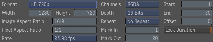
The following table lists the common property controls and their function.
| Property | Description |
| Format | Provides a selection of film formats. |
| Image Width/Height | Sets the width and height of the image produced by the generator node. |
| Image Aspect Ratio | Sets the image aspect ratio of the image produced by the generator mode. |
| Pixel Aspect Ratio | Sets the pixel aspect ratio of the image produced by the generator mode. |
| Rate | Sets the rate of the stream produced by the generator node. |
| Channels | Sets the number of channels of the images produced by the generator node. Possible channel combinations are:
|
| Depth | Sets the depth per channel (in bits) of the images produced by the generator node. Possible image depths are:
|
| Repeat | Determines how the generator node outputs its result outside its source time range. Possible modes are:
|
| Mark in/Mark out | Defines the total number of frames the node generates for the image. |
| Start Time/End Time/Offset | Defines the time range (and any offset required) where the generator node is to output a result. It follows global time. |
| Lock Duration | Locks the Start/End time values. |
Note: Height and Width are animatable attributes--see Setting Keys Manually and Validating and Applying the Expression String.
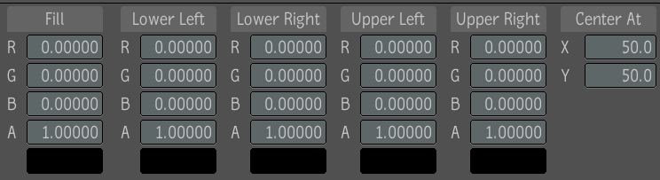
The Bilinear Ramp tool lets you create images with a variety of properties and in several formats. The Bilinear Ramp tool is comprised of five sets of color channel value fields that let you to generate a multi-color image based on RGBA values. One set of values is for generating the fill color, and four sets are for generating start and end ramped colors residing in a four-quadrant region of definition (ROD). The fill color is defined as those pixels residing outside the ROD. Two other controls let you to position the X and Y axes of the ramps at any location in the image.
Note: The following procedure assumes that you have a Schematic view and a Player view open.
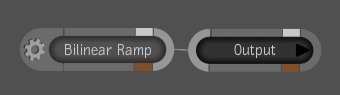
Drag the Bilinear Ramp tool from the Tools tab to the dependency graph in the Schematic view and attach it to the Output node.
 "Show full-size image")
Apply image properties--see Setting Image Generation Properties and Formats.
Adjust the color values in the Fill, Lower Left, Lower Right, Upper Left, and Upper Right.
Modify the location and direction of the X and Y ramps.
 "Show full-size image")
Note: You can also manipulate the linear ramp by clicking and dragging the horizontal and vertical bars.
 "Show full-size image")
Note: You can also type values directly into the value fields and press Enter.
Note: The Bilinear Ramp tool's Fill, Lower Right, Lower Left, Upper Right, Upper Left, and Center X and Center Y parameters are animatable by setting keyframes or using expressions--see Setting Keys Manually and Validating and Applying the Expression String.
The Checkerboard tool lets you create images with a variety of properties and in several formats. The Checkerboard tool is comprised of three sets of color channel value fields and X and Y Period fields. One set of values is for generating the fill color, and two sets are for generating X and Y colors residing in the region of definition (ROD). The fill color is defined as those pixels residing outside the ROD. Two other controls let you adjust the size and look of the checkerboard in the X and Y directions.
Drag the Checkerboard tool from the Tools tab to the dependency graph in the Schematic view and attach it to the Output node.

 "Show full-size image")
The Checkerboard tool UI appears.
Apply image properties--see Setting Image Generation Properties and Formats.
Adjust the Fill, Color values, and Period values by dragging inside the value fields.

 "Show full-size image")
Note: You may also type values directly into the value fields and press Enter.
The Color Source tool lets you create images with a variety of properties and in several formats. The Color Source tool is comprised of two sets of color channel value fields that allow you to generate a single color image based on RGBA values. One set of values is for generating the fill color and the other set is for generating the color residing in the region of definition (ROD). The fill color is defined as those pixels residing outside the ROD.
Note: The following procedure assumes that you have a Schematic and a Player view open.
Drag the Color Source tool from the Tools tab to the dependency graph in the Schematic view and attach it to the Output node.

 "Show full-size image")
The Color Source tool UI appears.
Apply image properties--see Setting Image Generation Properties and Formats.
Adjust the Fill and Color values by dragging inside the value fields.

 "Show full-size image")
Note: You may also type values directly into the value fields and press Enter.
Note: The Color Source tool's Fill and Color parameters are animatable by setting keyframes or using expressions--see Setting Keys Manually and Validating and Applying the Expression String.
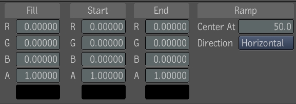
The Linear Ramp tool lets you create images with a variety of properties and in several formats. The Linear Ramp tool is comprised of three sets of color channel value fields that allow you to generate a multi-color image based on RGBA values. One set of values is for generating the fill color, and two sets are for generating start and end ramped colors residing in the region of definition (ROD). The fill color is defined as those pixels residing outside the ROD. Two other controls allow you to position the center of the ramp at any vertical or horizontal point in the image.
Note: The following procedure assumes that you have a Schematic and a Player view open.
Drag the Linear Ramp tool from the Tools tab to the dependency graph in the Schematic and attach it to the Output node.

 "Show full-size image")
The Linear Ramp UI appears.
Apply image properties--see Setting Image Generation Properties and Formats.
Adjust the Fill, Start, and End color values by dragging inside the value fields.
Modify the location and direction of the linear ramp.
 "Show full-size image")
Note: You can also manipulate the linear ramp by clicking and dragging the vertical bar.
 "Show full-size image")
Note: You can also type values directly into the value fields and press Enter.
Note: The Linear Ramp tool's Fill, Start, End, and Ramp Center parameters are animatable by setting keyframes or using expressions--see Setting Keys Manually and Validating and Applying the Expression String.
The Radial Ramp tool lets you create images with a variety of properties and in several formats. The Radial Ramp tool has three sets of color channel value fields that allow you to generate a multi-color image based on RGBA values. One set of values is for generating the fill color, and two sets are for generating start and end radially ramped colors arranged around a central axis region of definition (ROD). The fill color is defined as those pixels residing outside the ROD. Other controls let you to position the X and Y axes of the central ramp at any location, stretch the ramp vertically or horizontally, and define the falloff center point and range.
Note: The following procedure assumes that you have a Schematic and a Player view open.
Drag the Radial Ramp tool from the Tools tab to the dependency graph in the Schematic view and attach it to the Output node.

 "Show full-size image")
Apply image properties--see Setting Image Generation Properties and Formats.
Adjust the color values in the Fill, Start, and End fields.
Modify the location and direction of the X and Y ramps.
Adjust the middle and falloff ranges.

 "Show full-size image")
Note: You can also manipulate the radial ramps by left-clicking and moving them.
 "Show full-size image")
Note: You can also type values into the value fields and press Enter.
Note: The Radial Ramp tool's Fill, Start, End, and all associated Radial Ramp parameters are animatable by setting keyframes or using expressions--see Setting Keys Manually and Validating and Applying the Expression String.
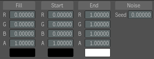
The Noise generating tool lets you add realism to computer generated images, or to simulate or match film grain. The generator creates an image of random pixels. The Noise generating tool is comprised of three sets of color channel value fields that let you to generate a multi-color image based on RGBA values. One set of values is for generating the fill color, and two sets are for generating start and end color values. You can also adjust the level and seed (method used to generate the noise).
Note: The following procedure assumes that you have a Schematic and a Player view open.
Drag the Noise tool from the Tools tab to the dependency graph in the Schematic view and attach it to the Output node.
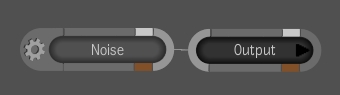
 "Show full-size image")
Apply image properties--see Setting Image Generation Properties and Formats.
Adjust the color values in the Fill, Start, and End fields.
Adjust the noise seed.
 "Show full-size image")
Note: You can also type values into the value fields and press Enter.
Note: The Noise tool's Fill, Start, End, and associated Seed parameters are animatable by setting keyframes or using expressions--see Setting Keys Manually and Validating and Applying the Expression String.
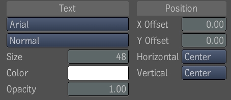
The Slate tool lets you add production information over an image or clip, which is useful during the review/approval stage of a project. Although Slate is not a full text tool, you can adjust the size, color, opacity, position, and duration of the text, as well as add a drop shadow. You can also animate the attributes of the text.
When adding information to a composition, you can use variables for the composition's name, date, time, frame number, timecode, and length. You can also enter your own information about the composition, such as the project title, camera, lens, film stock, and so on.

 "Show full-size image")
Note: The following procedure assumes that you have a Schematic and a Player view open.
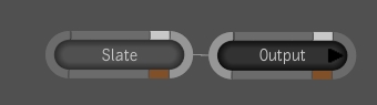
Drag the Slate tool from Image Generation folder in the Tools tab to the dependency graph in the Schematic and attach it to the Output node.
 "Show full-size image")
Apply image properties--see Setting Image Generation Properties and Formats.
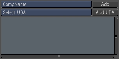
To add a variable to your composition, select a variable from the list, and click Add. You can add multiple variables.
 "Show full-size image")
| The composition's name appears in the Player. |
To enter information about your composition, select the type of information you want to add and click Add UDA. You can add as much or as little information as needed.

 "Show full-size image")
| The field appears in the text box, but not in the Player. |
Place the cursor inside the text field and edit the information.
Format the text and modify its location.
Hint: To scroll the list of fonts, use your mouse wheel or the scroll bar beside the list.
 "Show full-size image")
Add a drop shadow to the text by clicking Drop Shadow and setting its position, color, and opacity.
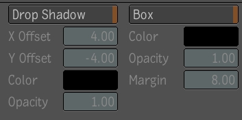
 "Show full-size image")
Add a background behind the text by clicking Box and setting the color, opacity, and margin.