Creates visual cross sections on selected surfaces or meshes. Those can be promoted to section data geometry.
Cross Section Editor Control Window
The Cross Section Editor control window contains all the needed tools to define, organize, edit and apply cross sections.
It lets you create and view different groups of cross sections on a surface, a trimmed surface, a mesh or a shell. The cross section groups are maintained and automatically updated with any change to the object. They are also saved with the model.
The Cross Section Editor features an interface that makes it easy to switch between cross section groups. You can create many cross section groups at once and apply them to any, or all, geometry.
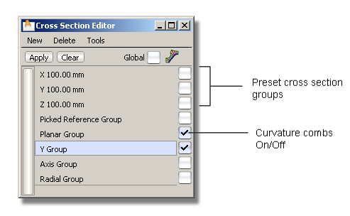
The editor contains three preset cross-section groups, perpendicular to the X, Y, and Z axes at 100 mm intervals.
To the right of each cross-section group’s name is a check box that lets you view or hide curvature combs on the cross-sections when the objects are selected.
The editor includes the following menus:
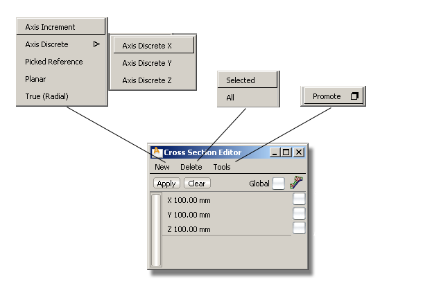
This menu lets you define sections in five different ways: Axis Increment, Axis Discrete (choice of X, Y or Z), Picked Reference, Planar, or True (Radial).
Choosing one of these options creates the cross section group, applies the cross section group to the selected geometry (or all geometry if Global is turned on) and opens the appropriate option window. See Cross Section Types below for details.
Delete the Selected cross-section group(s) only, or All cross-section groups (except the preset groups which cannot be deleted).
The only choice is to Promote the selected cross-section groups on the selected objects, to section data geometry. You can also pick individual sections after you enter the Promote tool.
These three controls lie below the menus:
Turn on Global (check mark) to apply the selected section groups to all visible geometry (surfaces and meshes). If you turn off Global (no check mark), any new section group you select is only applied to the picked (active) geometry.
Click the Apply button to apply the selected cross-section groups to newly selected geometry (surfaces and meshes).
Click the Clear button to remove the display of cross-sections from either the selected objects (if Global is off) or all objects (if Global is on).
If nothing is selected, all cross section groups are cleared from all geometry.
Choosing one of the five types of cross-sections from the New menu opens a control window. All control windows share the following options:
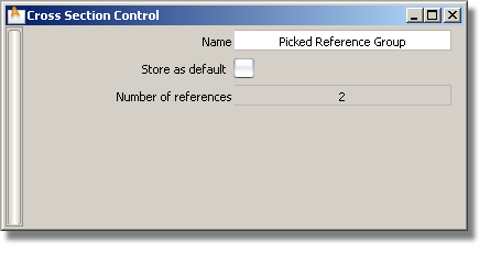
Shows the name of the cross section group that appears in the Cross Section Editor. Double-click this field to change the name.
Check this option to create a default section group (in addition to the X, Y, and Z section defaults). The cross-section group can then be applied across stages or across sessions. It remains in the Cross Section Editor until explicitly deleted.
The following three options only appear in the control window if the Curvature comb is checked on in the Cross Section Editor.
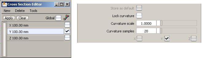
Turn on this option to prevent accidental modification of the cross sections curvature combs when using the global Comb Scale or Samples sliders from the Control Panel. (See Control Panel > Curvature ).
).
Scales the length of the curvature combs.
Specifies the number of equally-spaced quills that appear on the curvature combs.
Each type is described below along with the options that are specific to it.
These cross sections are perpendicular to the X, Y, and Z axes and are evenly spaced. They start from the origin and extend in both directions.
When selecting this option from the New menu, the following control window appears.

Turn on or off to view various combinations of cross sections perpendicular to the X, Y and Z axes.
The spacing between cross section lines along the X, Y, and Z axes.
If this option is checked, we use the bounding box of the picked objects to determine where to compute the cross sections, so that they show over the whole geometry independently of its position in space.
These options are only available when Auto Range is off.
The three fields represent the X, Y, and Z coordinates for the start and end of the range over which the cross sections are drawn.
If Start equals End, a single cross section line is created.
These are individually-created cross-sections that lie in a plane perpendicular to the X, Y or Z axis at a specific location. That X, Y or Z location is specified through the control window or by clicking the mouse.
When selecting this option from the New menu, the following control window appears.

Use this field to enter the location for a discrete cross-section. The new value is added to the list below and the field is reset to 0.0. A locator corresponding to the location is created on the model.
Double-click a value in the list to change it.
Click on a location in the list (the field turns blue and the locator is selected). Then click the Delete button to remove the corresponding cross-section.
These cross sections are created at the intersection between the geometry and selected section data or construction planes.
When selecting this option from the New menu, the following control window appears.
These cross sections are created at the intersection between the geometry and a (temporary) construction plane generated on the fly. You can also select an existing construction plane.
When selecting this option from the New menu, the following control window appears.
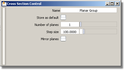
The number of cross sections created. The first one corresponds to the intersection of the construction plane with the surfaces. Additional cross sections are created in the direction of +Z axis of the construction plane, at Step size intervals.
The spacing between the cross sections.
If checked, cross sections are created on both sides of the defining plane. (For example, if Number of planes is set to 3, and Mirror planes is on, the total number of sections will be 5).
These cross-sections are created based on a driving curve you specify. Points, equally spaced by arc length, are placed on the curve to correspond to a given number of sections. A plane is then defined perpendicular to the tangent of the curve at each of these points. The cross-sections are created where the planes intersect the geometry.
The driving curve can be a free curve, a curve-on-surface, or a surface edge or isoparm. If all curves are tangent continuous, more than one driving curve can be selected.
When selecting this option from the New menu, the following control window appears.

Promoting visual cross sections to geometry
You can create section data from visual cross-sections by choosing Promote from the Tools menu in the Cross Section Editor. The following options are available.

If this option is checked on, cross-sections that are position (G0) continuous, and belong to the same intersecting plane, are merged into a single section curve. The Topology Distance tolerance from the Construction Options is used to determine if sections should be merged.
Fitting tolerance used to rebuild the internal NURBS curves as section data.
To create NURBS geometry from the section data, you must use the Curve Edit > Fit Curve tool.
tool.


