Provides adjustable settings to change the properties of orthographic cameras, perspective cameras (used for rendering), and image planes.
| Camera Editor subsections |
|---|
| Camera parameters |
| Film Back Properties |
| Camera/Window Properties |
| Digital Properties |
| Image Plane properties |
| Image Plane Parameters |
The camera parameters control the camera’s view. Perspective cameras have more parameters than orthographic cameras.
The camera whose parameters are currently displayed in the Camera Editor: Paint, Front, Bottom, Right, Top, Left, Back window cameras, or Camera (the perspective window’s camera). If you have additional cameras in your scene, they will also be listed in this menu, including cameras that are not used by any windows.
The Camera Editor window contains a number of subsections. Please select a subsection for more information about the options contained in that subsection.
The Camera Properties control the position and orientation of the current camera. The Twist and Perspective Gain parameters are only available for perspective cameras.
Makes the renderer automatically compute the near and far clipping planes (based on the bounding boxes of the objects in your scene) so that they include all visible objects in the current view frame.
By turning on Auto Render Clip, you can prevent certain types of image quality problems that can be caused by inappropriately set clipping planes.
Do not turn on Auto Render Clip when you are using shadow maps or if you are outputting depth files during rendering.
You can also produce this auto clipping behavior by editing the SDL file and setting the near clipping plane value to 0.
Clipping planes are ignored during raytracing.
Determines the camera’s view by defining the camera’s position (Eye), view point or focal point (View), and up vector end point (Up). Each parameter has three fields, corresponding to the XYZ coordinates for that parameter.
Positioning a camera by editing these parameters may be difficult, and is not recommended for positioning orthographic cameras. If you do edit these parameters, display the camera in the orthographic windows to help visualize the changes (see Display camera icons).
The tilt of the camera (from side to side) in degrees. The Up and Twist parameters define the same camera property in different ways. Changing one alters the other. For example, if you change the X Up value to 2, the Twist value automatically changes to -63.435. The slider range is -180 to 180. The default value is 0.
The Film Back Properties let you set the film size of the current camera by entering numeric values. You can also select a standard film size from the Predefined Film Backs list.
Make sure the Film Offset values are less than the Film Back values, or the rendered image may appear incorrect.
Focal length and angle of view
Focal length and angle of view are two different methods of defining the same lens property:
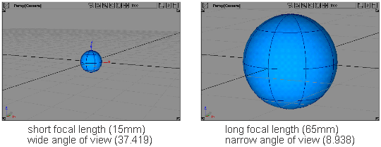
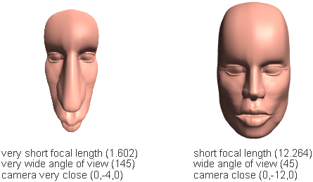
The horizontal angle of the view seen by the film. The valid/slider range is 0.2 to 179.
The angle of view is also known as the lens angle. It represents the width of the film back as seen through the lens, expressed as an angle.
The Angle of View value is related to the focal length value (either the Focal Length setting or the User Focal Length value), and the Film Back value:
Makes the renderer perform a depth of field calculation to vary the focus of objects based on their distance from the camera. If Depth of Field is ON, the following parameters become available: F-Stop, and User F-Stop. The default setting is OFF (no depth of field calculation is performed; all objects are in focus).
The depth of field calculation is a post-rendering process, and can take from tens of seconds to a few hours, depending on the size of the image, the camera parameters, and the depth values, but not the complexity of the scene.
Because depth of field changes with depth, your scene must reflect its real world size and the Main Units must be set properly in Preferences > Construction options (under Units : Linear).
Lets you set the camera’s f-stop either from a list of standard, real world f-stops (between 1.4 and 32), or by entering a value in the User F-Stop field (user). The default setting is user.
Small F-Stop values (such as 1.4) tend to give a very small depth of field. That means that the region at the specified distance from the camera that is in focus (the region between near and far) is small. Large F-Stop values (such as 32) tend to give a larger depth of field.
Automatically focuses the camera on the camera’s View point. If Auto Focus is OFF, the Focal Distance parameter becomes available, and the camera focuses at the Focal Distance value. The default setting is OFF.
If the View point is not between the near and far clipping planes, Auto Focus will focus the camera either at the near clipping plane or at the far clipping plane (whichever is closer to the View point). See ClippingNear/Far
The distance from the camera at which the camera focuses. The valid range is 0.001 to infinity. The slider range is 0.001 to 100. The default setting is automatically set to the Auto Focus value (based on the View point) when you set Auto Focus OFF.
If the Focal Distance value is not between the near and far clipping planes, the Focal Distance value will be automatically set to either the near clipping plane distance or the far clipping plane distance (whichever is closer to the Focal Distance value). See ClippingNear/Far.
A scaling factor applied to the Focal Distance value. This parameter lets you define the Focal Distance value in units other than feet (for example, meters) by setting the Scaling Factor value to the number of units in one foot. For example, if you wanted to define the Focal Distance value in meters, you would set the Scaling Factor value to 0.3048 because there are 0.3048 meters in one foot. The slider range is 0 to 100. The default value is 1.
The Scaling Factor parameter is the same as the SDL variable units_to_feet.
The Camera/Window Properties control how the camera’s view appears in the camera’s window.
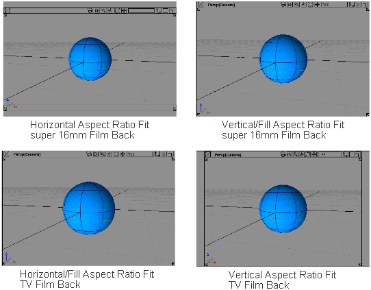
Controls how the camera’s window displays the camera’s view. If the shape of the camera’s window is not the same as the shape of the camera’s Film Back, then the window’s display can fit the camera’s view in one dimension only (Horizontal or Vertical). The default setting is Fill which automatically fits the camera view in the camera window (in either the horizontal or vertical direction) so that the camera view fills the window
Offsets the camera view in the camera window. The direction of the offset is determined by the padding created by the Aspect Ratio Fit setting, either horizontally (if Aspect Ratio Fit is Vertical or Fill), or vertically (if Aspect Ratio Fit is Horizontal or Fill). The valid/slider range is -1 to 1. The default setting is 0 (no offset).
The distance to the camera’s near and far clipping planes. The default values are 0.1 and 200.
For orthographic windows, the ClippingNear/Far values are distances along the axis that points into the screen. For example, if the Top window shows the XZ plane, then the ClippingNear/Far values are distances along the Y axis.
For perspective cameras, the Clipping Near/Far values are distances from the camera.
You cannot enter a ClippingNear/Far value less than 0.1 within Alias. However, you can enter a value less than 0.1 by editing the SDL file.
Make sure the ClippingNear/Far values are set so that the clipping planes just barely contain the contents in your scene (see Auto Render Clip). Setting the ClippingNear value very low or the ClippingFar value very high may produce image quality problems during rendering.
Creates a stereo pair of images of your scene during rendering. The two image files are named <filename>_left and <filename>_right. If Stereo View is OFF, only a single image of your scene is created during rendering. If Stereo View is ON, the Parallel Offset and Eye Offset parameters become available. The default setting is OFF.
The distance between the two cameras used to generate a stereo pair of images (when Stereo View is ON). Eye offset is also known as ocular separation, and represents the distance between the viewer’s two eyes. The two cameras are offset perpendicular to the View vector and the Up vector.
Objects that are closer to the camera than the focal point will appear to protrude from the screen when the stereo pair of images is viewed. Objects that are further from the camera than the focal point will appear to recede into the screen.
The greater the Eye Offset value, the greater the stereo effect, but the narrower the effective depth of the scene. If the Eye Offset value is too large, or the focal point is too close to the camera, your eyes will not be able to converge the two images into a stereo pair.
The Eye Offset value is measured in the same units that your scene uses. The slider range is 0 to 5. The default value is 1.
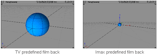
The Predefined Film Backs are standard film sizes that you can select for the current camera. Each predefined film back has a Film Back, Film Aspect, and Squeeze Aspect parameter; however, you can only edit the Film Back value (Alias does not use the Film Aspect and Squeeze Aspect values).
To select a predefined film back, simply click it. When you select a predefined film back, the Film Back values (under Film Back Properties) automatically change. To add a new predefined film back, click the Add button. To delete a predefined film back, select the film back from the list and click the Delete button. To edit a predefined film back, double click the field you want to edit, type in the new value, and press  (Windows) or
  (Mac).
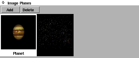
The Image Planes section of the Camera Editor contains a list of image plane swatches for the current camera, and buttons that let you add a new image plane to the camera or delete an existing image plane.
By default, a camera has no image planes, and no image plane swatches are listed. You can add one or more image planes to a camera using the Add button. The image planes are then listed in the Image Planes section of the Camera Editor, and the Image Plane Parameters for the active image plane become available. The active image plane is highlighted in white in the image plane swatch list. You can select an image plane by clicking on its swatch.
See Add or delete an image plane.
Lets you add a new image plane to the current camera by selecting an image file with the File Requestor.
You can also add an image plane to the active window’s camera by selecting File > Import > Image Plane (see Importing Image Planes in the Alias Interface section of the Basic Tools book).
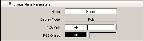
The Image Plane Parameters represent the parameters for the active image plane (the image plane that is selected in the Image Planes list).
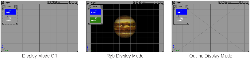
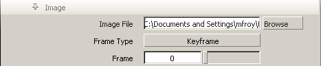
Controls how the image plane is displayed in the modeling windows and in the SBD window. The image plane will only render when Display Mode is either Rgb or Off. The default setting is Rgb.
| Outline | A rectangle with diagonals. |
| Rgb | Full 24 bit color image. |
| Off | No display. |
See RGB Mult.
A scaling factor applied to all colors in the image plane. That is, all colors in the image plane are multiplied by the RGB Mult color. For example, you can color correct an image plane that appears too green by setting the RGB Mult color to a shade of blue. The default color is white (no effect).
See RGB Offset.
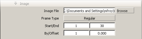
The image plane’s source image file name. If this file is part of a sequence (for example, image.1, image.2,...), then only the base file name is displayed (for example, image). Image File may be an absolute path (for example, /usr/3DCD/pix/image), or it may be a file name relative to the current project (for example, image).
Determines whether the image plane will use an animated sequence of image files (Regular or Keyframe), or a single image file (Off). The default setting is Off.
| Off | the image plane uses a single image file, even if the image file is part of a sequence |
| Keyframe | the image plane uses an irregular sequence of image files (see Keyframe Frame Type below) |
| Regular | image plane uses a regular sequence of image files (see Regular Frame Type) |
If you want to use an irregular sequence of image files as an animated image plane (for example, if the sequence only includes image files for frames 1, 7, 11, 14, 18, and 33), set Frame Type to Keyframe. The Frame and Offset parameters become available.
By keyframing (Animation > Keyframe > Set Keyframe ) the Frame parameter, you can create an animation curve for the image plane which you can edit in the Action Window. If you do not have an image file for every frame of your animation, then use the STEP tangent type when animating the image files (see Animation > Editors > Action Window
 ).
).
You can also use the Read button to automatically create keyframes for all available image files.
The frame of your animation at which the image plane displays the first image file of the sequence. The slider range is 0 to 100. The default value is 0.
For example, if the image plane files are named image.1, image.7, ..., image.33, and the Offset value is 7, then image.1 is displayed at frame 1 + 7 = 8 of the animation, image.7 is displayed at frame 7 + 7 = 14, ..., and image.33 is displayed at frame 33 + 7 = 40. In addition, image.1 is displayed at frames 1 to 7 because it is the first image of the sequence, and image.33 is displayed at frames 41 to the end of the animation because it is the last image of the sequence.
Scans your image file directory for images of the form image.# (where # is the image’s frame sequence number), and automatically keyframes those images at the correct frames. You can press the Read button again at any time to include any new image files in the animation. You can also edit the animation curve for the image plane’s Frame parameter in the Action Window.
For example, if image files exist for frames 1, 7, 11, 14, 18, and 33, and the Offset value is 7, clicking the Read button will automatically keyframe these images at frames 8, 14, 18, 21, 25, and 40.
The Read button is very useful if you do not know which frames you have available (for example, if someone else is generating keyframe pose images for you at the same time that you are building the animation).
If you want to use a regular sequence of image files as an animated image plane (for example, if the sequence includes image files for frames 1, 2, 3, 4, 5,..., 30), set Frame Type to Regular. The Start/End and By/Offset parameters become available.
By setting these parameters, you automatically create an animation curve for the image plane’s Frame parameter which you can edit in the Action Window.
The increment of each image file frame number (By), and the frame of your animation at which the image plane displays the first image file of the sequence (Offset).
For example, if the image plane files are named image.1, image.2, ..., image.30, and the Offset value is 7, then image.1 is displayed at frame 1 + 7 = 8 of the animation, image.2 is displayed at frame 2 + 7 = 9, ..., and image.30 is displayed at frame 30+7 = 37. In addition, image.1 is displayed at frames 1 to 7 because it is the first image of the sequence, and image.30 is displayed at frames 38 to the end of the animation because it is the last image of the sequence.
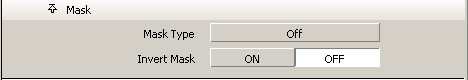
Image plane masking is similar to label masking (see Mask a label using an image file mask).
The Mask parameters let you mask the Image File so that only portions of the image are visible.
The method used to mask the image plane’s Image File. The default setting is Off (no mask).
| Off | no mask; the entire rectangular Image File is displayed |
| Image | the mask is taken directly from the Image File (for example, if the image contains transparency information) |
| File | the mask is taken from a separate image: the Mask File (see File Mask Type below) |
| Chroma-Key | the mask is based on a certain color, or a certain range of colors, in the Image File (see Chroma-Key Mask Type) |
If you want to use a separate image file to mask the image plane’s Image File, set Mask Type to File. The Mask File and Frame Type parameters become available.
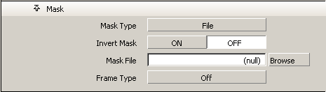
The name of the image file used as a mask by the image plane. Where the Mask File is white, the Image File will be visible. Where the Mask File is black, the Image File will not be visible. Where the Mask File is grey, the Image File will be partially visible. The Mask File is automatically positioned in the same location as the Image File.
Determines whether the image plane will use an animated sequence of mask files (Regular or Keyframe), or a single mask file (Off). The default setting is Off. The Mask parameter Frame Type is identical to Image parameter Frame Type (see Frame Type).
One use of animated Image File and Mask File is to view a pre-rendered walk cycle for a character and evaluate the character’s interaction with other characters.
See Mask a label using an image file mask.
If you want to mask certain colors, or a certain range of colors, in the Image File, set Mask Type to Chroma-Key. The Key Color, Hue Range, Sat Range, Value Range, and Threshold parameters become available.
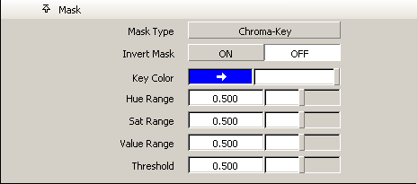
One use of chroma key masking is to mask out the blue background of live action that was filmed against a blue screen.
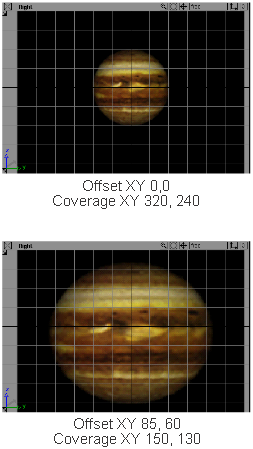
See Sizing and positioning an image plane.
The Image Placement parameters control how the Image File covers the camera view. For example, you may not want to display any bad edges that may be in your Image File, or you may want the image to occupy a very specific region of the screen.
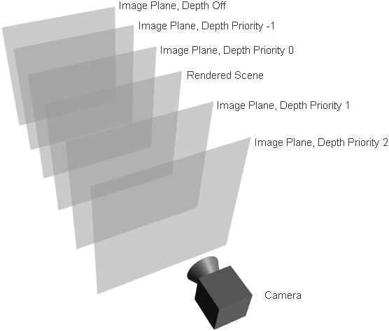
Determines whether the image plane appears in front of or behind your scene, and in front of or behind other image planes. If Depth is Priority, a numeric field becomes available.
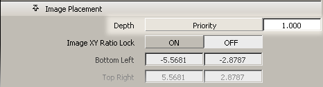
The value of the Priority numeric field determines the order the image planes appear in. Image planes with Priority greater than 0 will appear in front of the rendered scene. Image planes with Priority less than or equal to 0 will appear behind the rendered scene.