


Creates visual cross section lines on the selected surfaces and meshes, using one of five different methods, with the Windows > Editors > Cross Section Editor tool.
tool.
The editor lets you define groups of cross sections with specific characteristics, apply them to any geometry at any time, and even save them with your model.
You can also convert the visual cross-sections to section data geometry (using Tools > Promote in the Cross Section Editor).
To obtain NURBS curves, you must use the Curve Edit > Fit Curve tool on the section data.
The different types of cross-sections
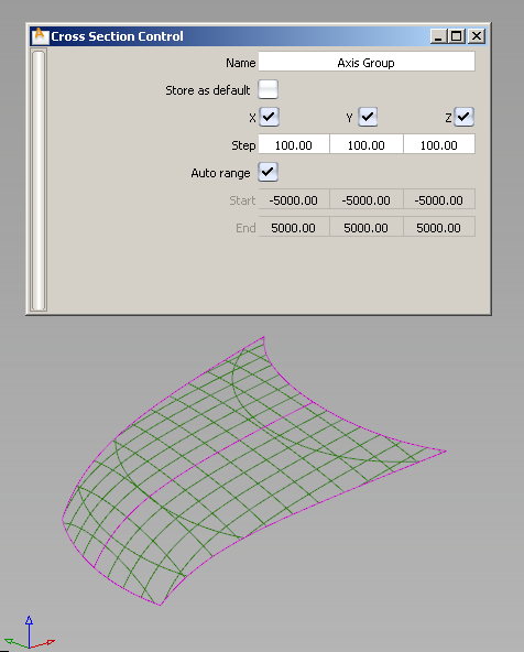
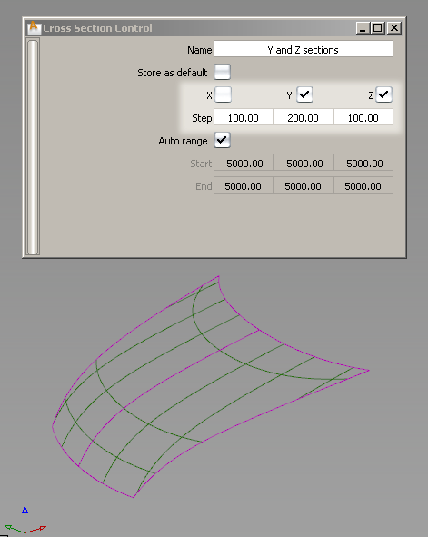
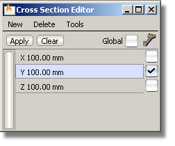
Cross sections are created in the X,Y or Z planes with a regular step size starting from the origin. For example, with a step size of 2.5 cm, the cross section specs are created at -2.5, 0.0, 2.5, 5.0... and so on.
When the Auto Range option is turned on (default), the cross sections are shown over the entire surface. Otherwise, you must explicitly set the range over which the cross sections should be displayed.
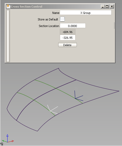
Cross-sections are individually created in a plane perpendicular to the X, Y or Z axis at a specific location. That X, Y or Z location is specified through the control window or by clicking the mouse in the view.
Cross-sections are created at the intersection between the geometry and a (temporary) construction plane generated on the fly. You can also select an existing construction plane.
Cross-sections are created based on a driving curve you specify, and the Number of planes option. Points, equally spaced by arc length, are placed on the curve to correspond to the number of sections. A plane is then defined perpendicular to the curve’s tangent at each of these points. The cross-sections are created where the planes intersect the geometry.
The driving curve can be a free curve, a curve-on-surface, or a surface edge or isoparm.
Visual cross-sections on surfaces have a different active and inactive color than visual cross-sections on meshes.
Visual cross-sections on objects that belong to a Pickable layer with an assigned color inherit that color, whether the objects are surfaces or meshes.
Visual cross-sections are also visible on Reference and Inactive layers, and their color matches the color defined for those states.
Wireframe anti-aliasing applies to visual cross sections. Turn anti-aliasing on and off through WindowDisplay > Anti-Alias > Wireframe Anti-Alias.)
When you toggle on a construction plane (Construction > Toggle Construction Plane ), Axis Increment (X, Y, Z) sections are re-drawn to match the new coordinate system. Other section types (discrete, planar, radial) maintain
their original location.
), Axis Increment (X, Y, Z) sections are re-drawn to match the new coordinate system. Other section types (discrete, planar, radial) maintain
their original location.
To create Axis Increment (X, Y, Z) cross sections
.
If Global is turned off and nothing is selected, you can still create cross section groups and apply them later. See To apply cross section groups.
Selected surfaces/meshes turn purple. The control window opens.
Cross sections appear on the geometry.
A new section group called Axis Group appears in the editor.
 (Windows) or
  (Mac).
The new name for the cross section group is displayed in the Cross Section Editor.
The default group remains in the Cross Section Editor even after you exit and re-launch Alias. To delete it, you must select it and choose Delete > Selected in the editor’s menu.
The cross sections update.
See Windows > Editors > Cross Section Editor for option details.
To create Axis Discrete cross sections
.
If Global is turned off and nothing is selected, you can still create cross section groups and apply them later. See To apply cross section groups.
Selected surfaces/meshes turn purple. The control window opens.
The section and a corresponding locator appear in the view.
A new value is added to the Section Location list.
A new section group called X Group, Y Group, or Z Group appears in the editor.
 (Windows) or (Mac).
The new name for the cross section group is displayed in the Cross Section Editor.
The default group remains in the Cross Section Editor even after you exit and re-launch Alias. To delete it, you must select it and choose Delete > Selected in the editor’s menu.
To create Picked Reference cross sections
.
If Global is turned off and nothing is selected, you can still create cross section groups and apply them later. See To apply cross section groups.
Selected surfaces/meshes turn purple. The control window opens.
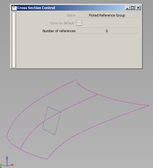
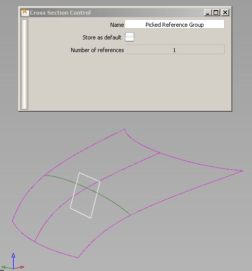
The control window displays how many reference items have been selected.
The cross-sections appear in the view.
A new section group called Picked Reference Group appears in the editor.
 (Windows) or (Mac).
The new name for the cross section group is displayed in the Cross Section Editor.
The default group remains in the Cross Section Editor even after you exit and re-launch Alias. To delete it, you must select it and choose Delete > Selected in the editor’s menu.
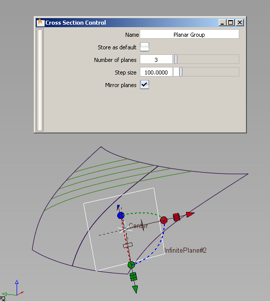
To create Planar cross sections
.
If Global is turned off and nothing is selected, you can still create cross section groups and apply them later. See To apply cross section groups.
Selected surfaces/meshes turn purple. The control window opens.
 tool. (See Create or edit a reference plane for more details.)
The construction plane appears, as well as the section it cuts through the geometry.
A new section group called Planar Group appears in the editor.
(Windows) or (Mac).
The new name for the cross section group is displayed in the Cross Section Editor.
The default group remains in the Cross Section Editor even after you exit and re-launch Alias. To delete it, you must select it and choose Delete > Selected in the editor’s menu.
The cross sections update.
See Windows > Editors > Cross Section Editor for option details.
The cross-sections update.
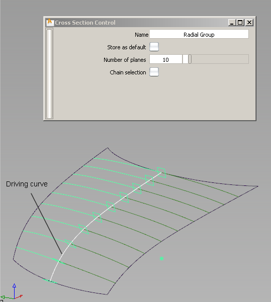
To create True (Radial) cross sections
.
If Global is turned off and nothing is selected, you can still create cross section groups and apply them later. See To apply cross section groups.
Selected surfaces/meshes turn purple. The control window opens.
If Chain selection is turned on, you can select a group of tangent continuous curves all at once.
Small planes, equally spaced by arc length, are displayed on the curve(s), corresponding to the number of sections. The planes are perpendicular to the curve’s tangent at each location. The default number of planes is 10.
Cross sections appear on the geometry, where it intersects the planes.
A new section group called Radial Group appears in the editor.
Cross sections are created perpendicular to the driving curve’s tangent, at equally spaced points.
(Windows) or (Mac).
The new name for the cross section group is displayed in the Cross Section Editor.
The default group remains in the Cross Section Editor even after you exit and re-launch Alias. To delete it, you must select it and choose Delete > Selected in the editor’s menu.
 key to add to the selection or the
  key to select all the section groups within a range.
If Global is turned on (check mark is visible and Apply button is greyed out), the selected section groups are applied to all visible surfaces and meshes. (If you import or create new geometry, or show hidden geometry, the selected section groups are applied to those as well.)
If Global is turned off (no check mark), selecting a section group only applies it to the selected surfaces and meshes.
If Global is turned off, click the Apply button to apply the selected cross section groups to those.
The cross sections update on the geometry.
See Windows > Editors > Cross Section Editor for details.
To change the visual cross section settings
The control window opens.
For the Planar type, you can also modify the construction plane.
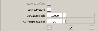
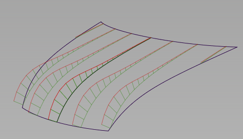
To create and change a curvature comb on a visual cross section group
The curvature combs appear in green on the model.
A Curvature scale slider, Curvature samples slider and Lock curvature checkbox appear in the control window.
 ).
).
To hide curvature combs on existing visual cross sections
To snap and measure to visual cross sections
The following objects will automatically snap to the visual sections when you position them by clicking a section:
You can also snap the following objects to visual sections by holding down the and  keys and clicking a section:
In addition, the following measurement tools work on visual sections:
Modifying surfaces with visual cross-sections causes those sections to update, in turn causing the measurement locators to update.
Clearing a visual cross-section group, or modifying its definition (through the control window) deletes the associated measurements.
To convert visual cross sections to section data geometry
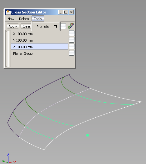
Section data is created for all active (highlighted) visual sections.
If Sort sections is turned on in the control window (default), X, Y, and Z sections are put in separate color-coded layers.
If Merge sections is turned on in the control window (default), cross-sections that are position (G0) continuous, and belong to the same intersecting plane, are merged into a single section curve.
See Promoting visual cross sections to geometry for details.