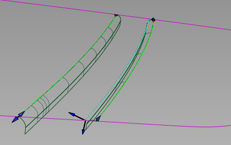
Creates the many surfaces that define a finished gap, along a set of tangent continuous surface curves, including the flanges (that define the edges) , the fillets between the panel and the edges, and an optional close-out surface at the bottom of the gap.
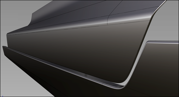
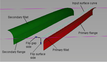
Example of a panel gap.
To build a gap within a panel surface, you need, at a minimum, one or more tangent continuous (G1) surfaces curves on the panel. Optionally, you can also build the gap between a set of G1 surface curves, and a separate set of surfaces. See Create panel gaps with rolled edges for more details.
As with the Fillet Flange tool, an imaginary "wall" surface is first built off the surface curves, to help define the primary fillet. (The wall is not actually added to the model.)
Instead of having explicit wall options like the Fillet Flange tool, Panel Gap uses the Primary Flange options to define the wall.
If the primary flange Type is set to Parting line, the wall uses the Primary Vector direction plus the Draft angle as the draft direction. If the primary flange Type is set to Sweep angle, the wall is based on the direction of the surface normal at the selected curve.
The primary fillet and flange are created in the same way as with the Fillet Flange tool.
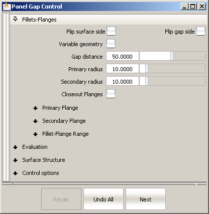
The primary fillet is always a circular fillet (constant radius fillet) and tangent continuous with the panel surface. You can specify its radius (Primary radius) in the control window. The fillet is built between the panel surface and the (imaginary) wall.
The location of the secondary fillet is calculated from the values of the Primary radius, Gap distance, and Secondary radius provided in the control window.
Specifies the type of manipulator that is created when you click the input curve.
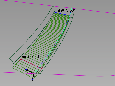
Gap – The gap manipulators control the width of the gap. They appear as straight lines across the gap.
Primary Vector – The primary vector manipulators control both the draft direction and the primary flange direction. These manipulators appear as purple arrows.
Secondary Vector – The secondary vector manipulators control the secondary flange direction. These manipulators appear as yellow arrows.
Primary Flange / Secondary Flange
The options to control the primary and secondary flange are the same, with the addition of a third Type called Relative to Primary for the secondary flange.
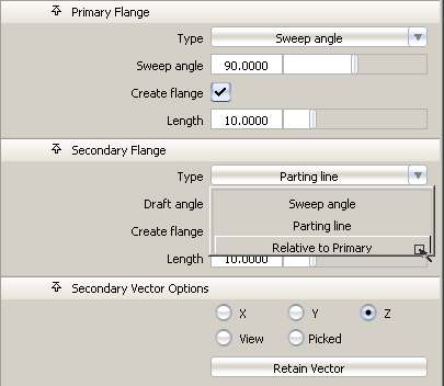
Sweep angle – The flange us defined by a Sweep angle, which is the angle between the flange and the input surface.
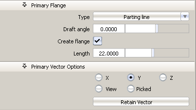
Parting line – The flange is defined by the direction of a vector (specified through the Primary/Secondary Vector Options) plus a Draft angle.
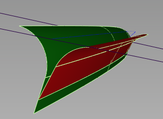
Relative to Primary – This option only applies to the Secondary Flange. It lets you change the Draft angle or Sweep angle of the secondary flange relative to the first flange. This is useful to create a gap with zero width and coincident flanges, as shown below.
These options only apply when Type for the corresponding flange is set to Parting line.
X, Y, Z – Select one of these to specify a pull direction along that axis.
View – Select this option to specify a pull direction normal to the current view. The vector is not drawn in the view windows.
Picked – Selecting this option lets you specify the name of an existing vector in the Picked Vector field, or pick the vector in the view. This vector defines the pull direction.
Refresh View Vector – This button only appears if View is selected. Click it to update the vector if the view has been modified.
Retain Vector – Click this button to create a vector construction object in the view windows. Unless you do this, the vector direction you specified is used by the tool, but you will not see and be able to re-use the vector.
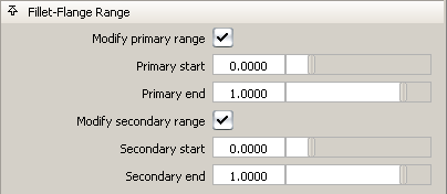
Checking on these boxes causes arrow manipulators to appear on the fillets. Drag these arrows to modify the extent of the fillets and flanges across the main panel. You can drag the arrows all the way to the edges of the input surfaces.
Primary and Secondary start / end sliders also appear in the control window and can be used instead of dragging the arrows. Setting the sliders to 0.0 and 1.0 resets the original extent.
These controls apply to both primary and secondary fillets and flanges simultaneously. They are the same as in Fillet Flange.
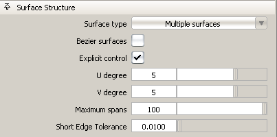
Single surface – A single fillet and flange surfaces are built on each side of the gap.
Multiple surfaces – The fillets and flanges are split at the boundaries of the input curves and surfaces.
Curves-on-surface created at the edges of the fillets (visible when Auto Trim is off) are segmented to correspond to the multiple fillet/flange surfaces.
If Surface Type is set to Multiple surfaces, this value specifies the maximum number of spans for each fillet and flange surface. If Surface Type is set to Single surface, it specifies the maximum number of spans for each piece of the original surfaces.
This option is only available when Explicit Control is checked, and Bezier Surfaces is not checked.
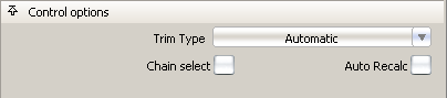
Off – Does not trim the panel surfaces.
Curves-on-surface – Places curves-on-surface on the panel surfaces at the fillets edges, without trimming.
Automatic – Automatically trims the panel surfaces to the edges of the fillets, provided the fillets extend to the ends of the surfaces. You may need to use the Fillet-Flange Range options to extend the fillets. This is the default.
Using the manipulators to create a variable gap
Each manipulator consist of two handles, one at each end. Click on a handle to change its value (it turns white) or simply
roll over it to see the value (it turns yellow). Hold  and click on a manipulator to remove it.
 .
.
.
. 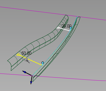
The gap widths between the edge of the panel and the first manipulator, as well as between the opposite edge of the panel and the last manipulator, are constant. The width between any pair of interior manipulator is interpolated.
. 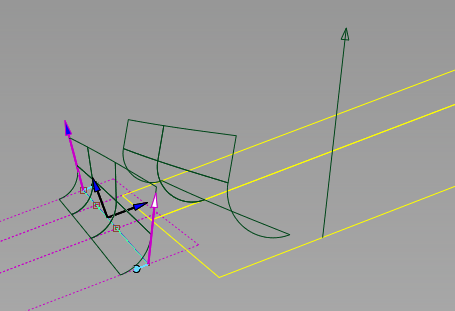
For both Primary Vector and Secondary Vector manipulators, the vector direction between the edges of the panel and the nearest manipulator remains constant. Between any pair of interior manipulators, the vector direction is interpolated.