


The Surfaces > Rolled Edge > Panel Gap  tool is the ultimate rolled edge tool, allowing you to create the many surfaces that define a finished panel gap, including
the flanges (that define the edges) , the fillets between the panel and the edges, and an optional close-out surface at the
bottom of the gap.
tool is the ultimate rolled edge tool, allowing you to create the many surfaces that define a finished panel gap, including
the flanges (that define the edges) , the fillets between the panel and the edges, and an optional close-out surface at the
bottom of the gap.
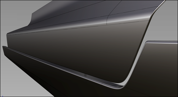
Example of a panel gap.
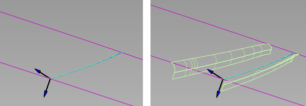
For input, you require, at a minimum, one or more tangent continuous (G1) surfaces curves on the panel. Optionally, you can also build the gap between a set of G1 surface curves, and a separate set of surfaces. This is shown below.
Two methods can be used to create the fillets and flanges of the panel gap.
 ❒ to open the control window.
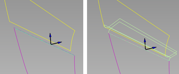
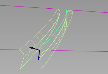
The curve is highlighted in green, and the surface turns pink.
The surfaces turn yellow.
Primary and secondary fillets and flanges are built. The panel surface is automatically trimmed to the edges of the fillets to create the gap.
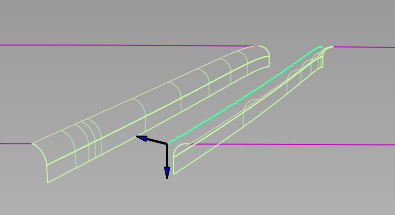
Gap built along a curve-on-surface within a single panel surface
The four surfaces are recalculated.
After modifying fillet radii, flange angle and length, and gap distance.
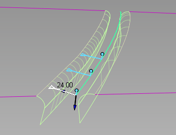
The fillets and flanges have construction history, so modifying your input curves will cause those output surfaces to update.
To modify the panel gap after exiting the tool, choose Object Edit > Query Edit and pick one of the output surfaces (fillets or flanges) to re-invoke the tool in the usual way.