Surfaces > Rolled Edge > Fillet Flange


Creates a fillet and a flange to refine the edges of a surface model.

The Fillet Flange tool provides you with automatic functionality that creates a finish on the edges of a surface model. By using one or more of the following: edge, curve-on-surface, boundary edge, or iso-parametric line, the tool creates a temporary, imagined wall used for construction only on the selected geometry. This wall can be based on a pull direction vector or on the surface normal at the selected geometry. Using this wall and the input geometry, the tool creates a surface fillet. Additionally, the Fillet-flange tool creates a linear extension called a Flange on the fillet. This extension can be defined by a sweep angle or a vector plus a draft angle.

Fillet Flange Control

Wall

Type

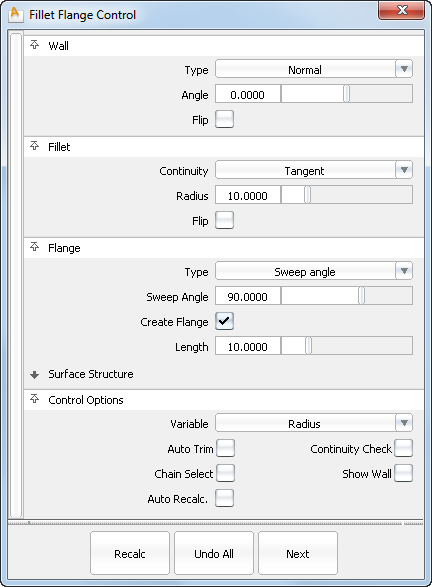
Set to either Draft or Normal. In Draft mode, the wall is defined by a pull direction vector plus a draft angle. Wall (for both Draft and Normal) defines the configuration of the fillet tangent. For Draft, a pull direction vector must be picked. The vector is highlighted in light blue (the same color is used for showing the wall). Normal builds a normal-based wall.

Angle/Draft Angle

The angle to the input surface normal at each point of the input curves, or the Draft Angle if Draft has been selected as the Type

Flip

Enables you to put the wall on top of or underneath the surfaces.

Draft Vector Options

These options only apply when Wall Type is set to Draft.

X,Y, Z

Select one of these to specify a pull direction along that axis.

View

Select this option to specify a pull direction normal to the current view. The vector is not drawn in the view windows.

If the current view is changed, click Refresh View Vector to update the vector.

Picked

Selecting this option lets you specify the name of an existing vector in the Picked Vector field, or pick the vector in the view. This vector defines the pull direction.

Refresh View Vector

This button only appears if View is selected. Click it to update the vector if the view has been modified.

Retain Vector

Click this button to create a vector construction object in the view windows. Unless you do this, the vector direction you specified is used by the tool, but you will not see and be able to re-use the vector.

Fillet

Continuity

Choose either Tangent or Curvature continuous to the base surfaces.

If Curvature is selected, Use Peak Curvature options can be set (see below).

Radius

Defines the radius of the fillet. You can create a variable radius interactively by adding more radius manipulators along the curve.

Flip

Enables you to flip the fillet on the other side of the wall. This option is grayed out if at least one of the input curves is an edge, and thus, it’s possible to build a fillet only on one side of the wall.

Use Peak Curvature

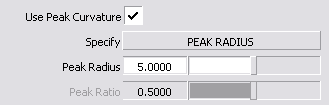
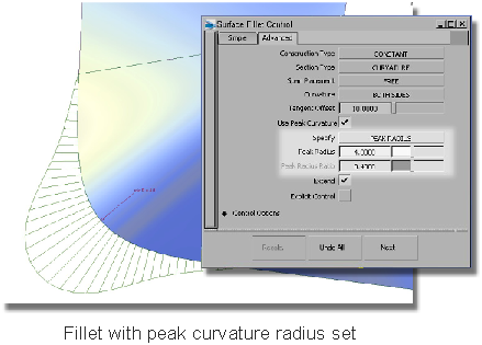
If Continuity is set to Curvature, check on Use Peak Curvature to set its options.

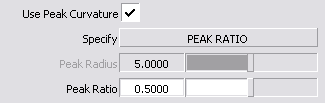
The Specify parameter is only visible if a single radius manipulator is used. If it is visible, you can specify either a Peak Radius or a Peak Ratio. If the fillet has more than one radius, you can only specify the Peak Ratio.

The Peak Ratio is the ratio of the Peak Radius to the Radius, and can be used for either variable or fixed radius fillet.

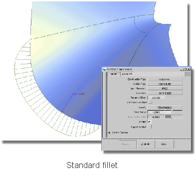
The following illustration shows the difference peak curvature can make to a fillet.

Flange

Type

Set to either Sweep Angle or Parting Line. Sweep Angle defines where along the fillet the flange will be tangent to the fillet. Parting Line uses a vector and draft angle that determines the direction of the flange.

If you select Parting Line, you must pick a vector or specify it through the Parting Line Vector Options, unless Wall Type is set to Draft, in which case the draft vector (shown in blue) will be used as the parting line pull direction by default. To specify a different vector for the parting line, Shift-pick it, or use the Parting Line Vector Options.

Sweep Angle or Draft Angle

Provides a slider to control the angle. The default is 90 degrees for Sweep, and 0 for Draft angle. Either angle can be variable.

Create Flange

Determines whether or not a flange will be built off the edge of the fillet. Note that the fillet will be trimmed according to the Sweep Angle or Parting Line settings, even if Create Flange is off.

Length

Determines the length of the flange that will be built, if Create Flange is on. Length can be variable.

Parting Line Vector Options

These options only apply when Flange Type is set to Parting Line.

X,Y, Z

Select one of these to specify a pull direction along that axis.

View

Select this option to specify a pull direction normal to the current view. The vector is not drawn in the view windows.

If the current view is changed, click Refresh View Vector to update the vector.

Picked

Selecting this option lets you specify the name of an existing vector in the Picked Vector field, or pick the vector in the view. This vector defines the pull direction.

Refresh View Vector

This button only appears if View is selected. Click it to update the vector if the view has been modified.

Retain Vector

Click this button to create a vector construction object in the view windows. Unless you do this, the vector direction you specified is used by the tool, but you will not see and be able to re-use the vector.

Surface Structure

Surface Type

Single surface – A single fillet surface is built.

Multiple surfaces – The fillet is split at curve boundaries, which also include surface boundaries, since a curve cannot span more than one surface.

Curves-on-surface created at the edges of the fillets (visible when Auto Trim is off) are segmented to correspond to the multiple fillet surfaces.

Bézier Surfaces

This option only appears if Surface Type is set to Multiple surfaces. If it is checked on, each surface will be a Bézier patch.

Bézier patches have a single span, and their maximum degree in the U direction is set through the Explicit Control section. The default is degree 5.

Explicit Control

Gives you controls of the surface degree and maximum number of spans in the fillet and flange surfaces.

(Length) U Degree

The degree of the fillet and flange surface in the U direction (that is along the edge). Enter a whole number from 2 to 9. This option is only available when Explicit Control is checked.

(Section) V Degree

The degree of the fillet surface in the V direction. Enter a whole number from 3 to 6. This option is only available when Explicit Control is checked.

NoteThe degree of the flange surface in the V direction is always 1.
Max. Spans

If Surface Type is set to Multiple surfaces, this value specifies the maximum number of spans for each fillet and flange surface. If Surface Type is set to Single surface, it specifies the maximum number of spans for each piece of the original surfaces.

This option is only available when Explicit Control is checked, and Bézier Surfaces is not checked.

Short Edge Tolerance

In the case of cross-knot insertion, the system will not allow spans of a linear distance less than the Short Edge Tolerance.

Control Options

Note that only one of the three parameters can be variable. For example, it is not possible to create a variable radius fillet with a variable length flange.

Variable

Gives you the ability to interactively modify the Flange Length, Flange Angle, or Radius.

Auto Trim

Choose whether to have the surfaces automatically trimmed, or just to place the curves-on-surface.

Continuity Check

Choose whether to get visual feedback about continuity (set in the Fillet section). Green indicates success; yellow indicates that the continuity condition has not been met.

Chain Select

If this box is checked, selecting a surface curve also selects all other surface curves that are tangent continuous with it.

Show Wall

Displays the imaginary wall that is used in the calculation of the fillet.

Auto Recalc

Choose between updating changes by selecting the Recalc button, or automatically updating changes.

Tip

If Auto Recalc is set off, use the spacebar to press the Recalc button.

To extend a Fillet flange

You can specify whether a fillet surface needs to be extended along the rail to reach the boundary of the input surface at each end of the rail. To toggle an extension at a rail end, click the green arrow appearing at that end. The arrow is shown in light green when extension is on. If the rail is closed, that is, its endpoints coincide, extension is not useful, and, therefore, the arrows are not shown.

To control the variable parameter in Fillet flange

The variable parameter (radius, flange angle, or flange length — as specified by Variable in the control window) is controlled using a set of manipulators in the modeling window. Only one of the parameters can be varied: the other two are held constant.

Each manipulator consists of two handles — the rail slider and the value handle — only one of which can be active at a given time. The active handle is shown in light blue. The rail slider, a "ball" sliding along the rail, indicates the position on the rail where the value applies. The value handle, an approximate cross section of the future surface, controls the value of the parameter at this point.

The value of the active handle is shown on the prompt line.

For all of the following operations, use the , unless stated otherwise.

To activate a handle, click it.

To de-activate the currently active handle and switch back to the picking mode, click anywhere on the screen (without dragging the mouse).

To add a new manipulator, click the desired point on the rail.

To move a manipulator, drag the slider using the . Alternatively, activate the slider and type in the position (in the range from 0 to 1) along the rail.

To adjust the parameter value, click and drag the value handle. Once the handle is active, the mouse can be dragged anywhere on the screen. Alternatively, activate the handle and type in the value in current units.

To delete a manipulator, Shift-right click it.

If a single manipulator is used, the parameter is constant, and its value can also be adjusted in the control box. As soon as another manipulator is added, the value in the control box is grayed out.

See Also