Creates a transition surface between two surfaces or sets of surfaces.
This pop-up menu controls the type of fillet.
Radius – Produces a rolling-ball fillet, where you control the radius value(s), but not the width of the fillet, or the position of the tangent lines.
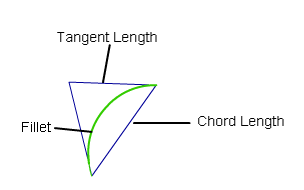
Chord – Lets you control the distance between the two edges of the fillet, instead of the radius. Use the Chordal Length (or Tangent Length) option to set the distance to maintain.
This pop-up menu controls the shape of the fillet’s cross-section.
Bias – Creates a fillet with a peak radius and tangent offset, the center of which is biased toward (closer to) one set of surfaces.
G2 Curvature – Maintains curvature continuity (G2) with both sets of surfaces. G2 continuity means that the curvature (which is the inverse of the radius of curvature) is the same on both sides across the fillet’s boundaries.
G3 Curvature – Maintains G3 continuity with both sets of surfaces. G3 continuity means that the curvature’s rate of change is the same on both sides across the fillet’s boundaries.
When calculating the fillet, the V degree is adjusted so that the surface has enough CVs to provide the required continuity on both sides. Degree 5 is needed for G2 Curvature and degree 7 is needed for G3 Curvature.
Lead – Creates a fillet with a peak radius and tangent offset that define the point of contact with the input surfaces. This type maintains tangent continuity with the surfaces on either side.
Circular – Creates a fillet with circular cross-section, tangent to both sets of surfaces. This type maintains tangent continuity with the surfaces on either side.
This option is only available when the Section Type option is set to Bias , G2 Curvature or G3 Curvature.
None – Do not maintain curvature continuity.
Side 1, Side 2 – Make the fillet surface curvature continuous with the first or second set of surfaces.
Both: Make the fillet surface curvature continuous with both sets of surfaces.
Radius, distance, and surface controls
When Construction Type is Radius, and Variable Fillets is checked on, this is the radius of a constant radius fillet surface that Alias uses as a basis for you to specify the various radii for the final fillet. You will set the final fillet’s radii at different points along the surface.
When Section Type is Circular, this is the radius of the fillet.
When Section Type is Lead, this is the radius around the centerline of the fillet.
When Section Type is G2 Curvature or G3 Curvature, this is the radius the tool will attempt to achieve while maintaining G2 or G3 curvature continuity.
The Peak Radius slider appears only when Section Type is Bias or Lead, and Specify is set to Peak Radius. The peak radius is the minimum radius that the fillet is allowed to have at the top.
The Center Radius slider appears only when Section Type is G2 Curvature or G3 Curvature, and Specify is set to Center Radius. The center radius is the radius at the arclength center of the fillet.
For Bias and Lead section types, choose whether you want to specify the Peak Radius or the Knee Ratio. For G2 and G3 Curvature section types, choose whether you want to specify the Center Radius or Tangent Offset. Those values offer different ways of specifying the peak/center radius or lead distance.
This option and its related parameters are only visible if Construction Type is Radius.
This is the ratio between Center Radius and Tangent Offset that is Form Factor = Center Radius / Tangent Offset.
It is only available when Section Type is G2 Curvature or G3 Curvature.
In the example below, we choose to specify the Tangent Offset, so increasing the Form Factor automatically increases the Center Radius.
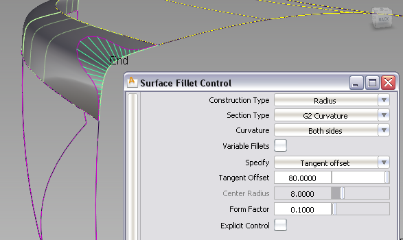
Form Factor set to 0.1, creating a small center radius and a sharper bend in the fillet.
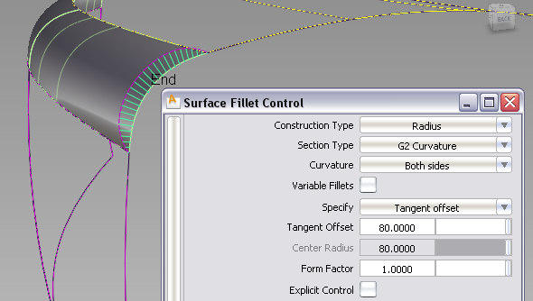
Form Factor set to 1.0 creating a large center radius and a near-circular fillet shape.
If Variable Fillets is checked on, the Center Radius control becomes unavailable. In this case, the Form Factor directly controls the center radius, hence the shape of the fillet at its peak. The larger the value, the larger the center radius, and the closer the fillet's section approaches a circular shape.
These options are only available when Explicit Control is turned on.
If Surface Type is set to Multiple surfaces, this value specifies the maximum number of spans for each fillet surface. If Surface Type is set to Single surface, it specifies the maximum number of spans inside each pair of boundaries between the original surfaces.
This option is only available when Explicit Control is checked, and Bézier Surfaces is not checked.
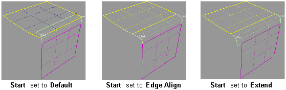
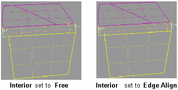
Controls how the fillet surface(s) edges (in the V direction) meet up with the edges of the boundary surfaces.
Edge align – The tool tries to colinearly align the fillet surfaces’ edges or isoparms (for single surface) to the edges of the boundary surfaces in the V direction.
Extend – The fillet is extended so that it reaches to the end of the longest boundary surface, at its start and/or end.
Default or Free – The edges (in the V direction) of the fillet meet the boundaries at a 90 degree angle.
Single surface – A single fillet surface is built.
Multiple surfaces – Multiple surfaces, corresponding to the boundaries between the original surfaces, are created. (Extra spans are added if necessary, and subject to Max. Spans, to meet tangent or curvature requirements.) This gives you much lighter fillet surfaces and better continuity with the original surfaces.
If curves-on-surface are created at the edges of the fillets (see Trim Type option below) they are segmented to correspond to the multiple fillet surfaces.


 key can be used to interrupt lengthy surface fillet computations.