Creates a new surface from up to 8 boundary curves.
The N-sided tool does the following:
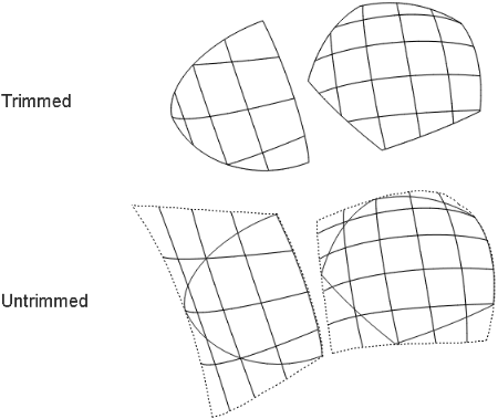
- Creates a normal (four-sided) NURBS surface that simulates a blend between the boundary curves.
- Trims the surface using the boundary curves to create the appearance of a surface with up to 8 sides.
Unlike the tool, triangular surfaces created by are not degenerate (that is, they do not have a zero-length side). The surface is only trimmed to appear triangular.
To create a surface with up to 8 sides
- Double-click the
 icon, or choose ❒ from the tool palette.
The window appears.
- Click the first boundary curve.
- You can use free curves, isoparametric curves, curves on surface and/or trim edges.
- To maintain continuity with another surface, you must pick an isoparametric curve or trim edge on that surface, not a construction
curve used to create that surface.
- Click each remaining curve (up to a total of 8) in clockwise or counter-clockwise order.
- If two adjacent boundary curves do not intersect, the tool averages their endpoints.
- If a curve intersects the first curve, creates the surface. Otherwise it displays the button and allows you to continue selecting curves.
- If you have selected all the boundary curves, click .
- Use the options in the window to set the continuity you want at each edge (see below).
To edit the construction history of an N-sided surface
- Pick the surface you want to edit.
- Click the icon, or choose from the tool palette.
The window appears.
- Use the curve modification tools (in the , , and palettes) to reshape the curves used to create the surface, and use the window to change the surface creation options.
Tips and notes
- For best results, use the snapping tools to make sure the curves intersect at their endpoints. This is not required, but it
makes the resulting surface more predictable.
- If you want to see only the effects of the options, set all the edges to continuity, since free edges have the fastest interaction.
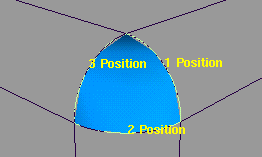
- The N-sided tool does not use labels to show whether the desired continuity was achieved. Instead you must look in the section of the window.
Click an edge named in the window to view the continuity feedback for that edge.
Lines of text indicate whether continuity was achieved. If it was not achieved, text boxes show how far out of tolerance the
current edge is for each type of continuity.
N-sided Control options
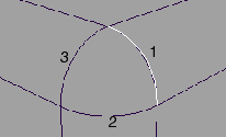
Continuity table
The Continuity Table displays one row for each boundary curve involved in the N-sided operation.
- Use the pop-up menu next to each curve to set the level of continuity across that boundary.
- Use the pop-up menu above the table to set the level of continuity across all curves at once.
-
-
– This edge is free to move if required by another edge’s continuity.
– Only keep positional continuity. This is the default.
– Try to keep tangency with a surface that shares this edge.
– Try to keep curvature continuity with a surface that shares this edge.
If the number of sides is not four, all boundary curves are automatically rebuilt to create N-sided trimmed surfaces. In this
case, the checkboxes are disabled.
The controls can only be used on four-sided (that is non-trimmed) surfaces:
- Click the checkboxes at the end of each row to rebuild the curves to reduce data and improve parameterization.
- Use the pop-up menu to set rebuild on or off for all the curves at once.
-
-
This option controls the degree of the curve on surface used to trim the new surface.
– The trim edges will be linear curves (degree 1).
– The trim edges will be cubic curves (degree 3).
Note that is much faster than .
-
-
This slider controls the degree of the new surface (from 1 to 7). The default is 3.
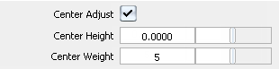
Center Adjust Options
These options let you push or pull the surface toward or away from a center point. and only appear when is on.
-
-
Display the center adjustment sliders and a distance locator on the model.
-
-
Increase or decrease the distance of the locator along the surface normal. This has the effect of pulling on or pushing in
the center of the surface.
-
-
Increase or decrease the influence of the locator on the surface. Decreasing this value increases the distance between the
center point you specify and the actual center point on the surface. The locator displays this distance.
Surface Continuity Feedback
-
-
Maximum number of spans the tool can insert in both U and V (on the initial untrimmed surface), as it tries to achieve continuity.
If the tool cannot achieve tangency without inserting more than the allowed number of spans, it displays an error in the prompt
line.
-
-
Use this slider to adjust the amount of smoothing to correct bumps and bulges. A higher weight smooths more.
-
-
Click an edge name in the window to view the continuity feedback for that edge.
Lines of text indicate whether continuity was achieved. If continuity was not achieved, text boxes show how far out of tolerance
the current edge is for each type of continuity.
For example, if an edge is 1 degree from tangency, and the tangency tolerance is 0.1 degrees, the tangent continuity feedback
line shows 0.9 degrees.
Control Options
-
-
Save the history of the new surface for later editing. If you turn on, you can modify the curves that were used to create the surface, and the surface will update.
-
-
Update the new surface automatically as you change the values in the window.
Buttons
-
-
Recalculate the surface with the current values in the window.
-
-
Finish the current surface and prompt for new curves.