


Fillets create a transition surface between two surfaces or sets of surfaces.
Create a fillet surface between existing surfaces
 ❒.
❒.
If you use a pick-box to select the second set of surfaces, it will not accidentally re-select any surfaces from the first set.
An arrow appears for each set of surfaces, indicating on which side of the surfaces the fillet will be built. The software makes an educated guess about where you intend to build the fillet, and orients the arrows accordingly.
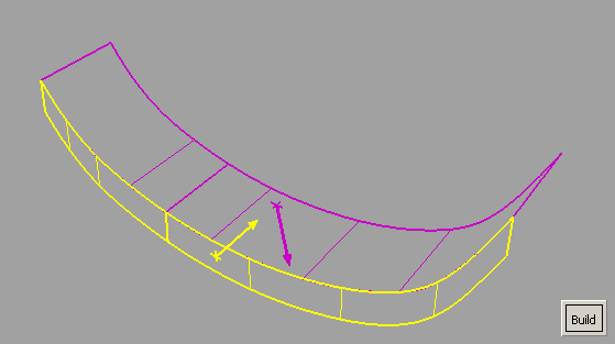
The fillet is built on the side of the surfaces indicated by the arrows.
If Surface Type is set to Multiple surfaces and curves-on-surface are created at the edges of the fillets (see Trim Type option) those curves-on-surface are segmented to correspond to the multiple fillet surface boundaries. To create the curves-on-surface as a single piece (for each surface), set Surface Type to Single surface
Create a fillet surface between surface curves
Freeform blend lets you create a fillet between surface curves (surface boundaries, trim edges, Isoparametric curves or Curves-on-surface).
In other words, you use surface curves on the two sets of surfaces to define the contact lines at the ends of the fillet.
 ❒.
❒.
The first set of curves is highlighted in purple.
The second set of curves is highlighted in yellow.
(This is not necessary if Auto Recalc. is turned on in the option window.)
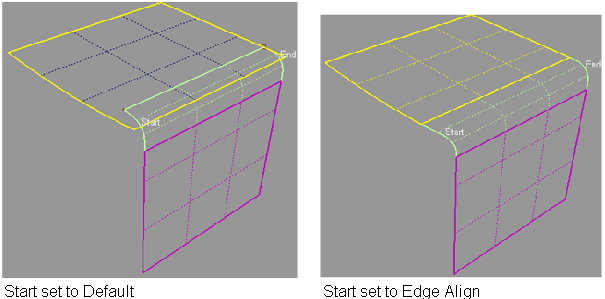
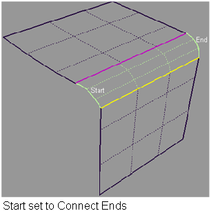
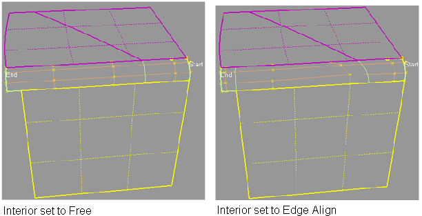
Adjust the alignment of the edges of the fillet/blend surfaces
Use the options in the Flow Control section to control how the blend surface(s) edges (in the V direction) meet up with the edges of the boundary surfaces.(
See Surfaces > Multi-Surface Blend > Freeform Blend).
You can adjust the alignment of the start, end, and (if more than one blend surface) interior edges.
Try lowering the fillet radius. Often the fillet does not build simply because there is not enough room to create the radius set in the options.
The default is to automatically trim the surfaces back to the new fillet surface. Use the Trim Type option in the control window to have the fillet tool only create curves-on-surface (but not trim), or turn trimming off completely.