Previously called Freeform fillet, Freeform Blend enables you to create a transitional surface based on two input contact lines.
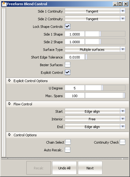
Choose Position, Tangent, G2 curvature or G3 curvature to determine the type of continuity that will be used between the blend surfaces and primary surfaces. The continuity settings can be specified independently along both sets of boundaries.
G2 curvature continuity means that the curvature (which is the inverse of the radius of curvature) is the same on both sides across the blend surfaces’s boundaries.The V degree of the blend surface is adjusted so that the surface has enough CVs to provide the required continuity on both sides. Degree 4 is needed for G2 continuity on one side, and degree 5 is needed for G2 continuity on both sides
G3 curvature continuity means that the curvature’s rate of change is the same on both sides across the blend surfaces’s boundaries. The V degree of the blend surface is adjusted so that the surface has enough CVs to provide the required continuity on both sides. Degree 6 is needed for G3 continuity on one side, and degree 7 is needed for G3 continuity on both sides.
Provides control over the “looseness” or “tightness” of the blend surface toward the first boundary. If the value is greater than 1.0, the result is a blend that fits tighter to the corner of the input surfaces; if the value is less than 1.0, the result is a rounder blend that fits closer to the edge of the first surface.
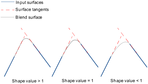
Provides control over the “looseness” or “tightness” of the blend surface toward the second boundary. If the value is greater than 1.0, the result is a blend that fits tighter to the corner of the input surfaces; if the value is less than 1.0, the result is a rounder blend that fits closer to the edge of the second surface.
If you choose Single surface, a single blend surface is built. If you choose Multiple surfaces, multiple surfaces, corresponding to the boundaries between the original surfaces, are created. (Extra spans are added, if necessary, to meet tangent or curvature requirements.) This gives you much lighter blend surfaces and better continuity with the original surfaces.
These options are only available when Explicit Control is checked.
If Surface Type is set to Multiple surfaces, this value specifies the maximum number of spans for each blend surface. If Surface Type is set to Single surface, it specifies the maximum number of spans inside each pair of boundaries between the original surfaces.
This option is only available when Explicit Control is checked, and Bézier Surfaces is not checked.
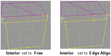
Controls how the blend surface(s) edges (in the V direction) meet up with the edges of the boundary surfaces.
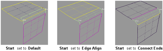
Edge align – The tool tries to colinearly align the blend surfaces’ edges or isoparms (for single surface) to the edges of the boundary surfaces in the V direction.
Connect ends – The edges of the blend surfaces meet the start and/or end points of the boundaries exactly.
Default or Free – The edges of the blend surface(s) (in the V direction) meet the boundaries at a 90 degree angle.