Lets you create one or many transitional surface(s) between multiple continuous surface boundaries, by specifying any number of cross-sections (profile curves) between the primary surfaces.
The primary surfaces’ edges may be trimmed, untrimmed, curves on surface, or isoparms.
You can place any number of profile curves (cross-sections) at any point between the primary surfaces’ boundaries. Profiles can be any type of curves, including blend curves and surface boundaries.
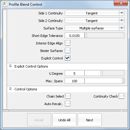
Choose Position, Tangent, G2 Curvature or G3 Curvature to determine the level of continuity between the blend surfaces and primary surfaces. The continuity settings can be specified independently along both sets of boundaries.
G2 curvature continuity means that the curvature (which is the inverse of the radius of curvature) is the same on both sides across the blend surfaces’s boundaries.The V degree of the blend surface is adjusted so that the surface has enough CVs to provide the required continuity on both sides. Degree 4 is needed for G2 continuity on one side, and degree 5 is needed for G2 continuity on both sides
G3 curvature continuity means that the curvature’s rate of change is the same on both sides across the blend surfaces’s boundaries. The V degree of the blend surface is adjusted so that the surface has enough CVs to provide the required continuity on both sides. Degree 6 is needed for G3 continuity on one side, and degree 7 is needed for G3 continuity on both sides.
If you choose Single surface, a single blend surface is built, with isoparms that line up with the boundaries of the primary surfaces, on both sides.
If you choose Multiple surfaces, multiple surfaces are created, breaking at the boundaries between the primary surfaces, as long as their edge in the U direction is longer than the Short Edge Tolerance. Extra spans are added, if necessary, to meet tangent or curvature requirements.
This tolerance controls the minimum length of a blend surface (in the U direction), or the minimum distance between isoparms for a single surface.
Blend surfaces will only break at boundaries if their U-length is larger than this tolerance. The distance between the isoparms of a single blend surface will be larger than this tolerance.
If this box is checked, the tool tries to colinearly align the blend surfaces’ edges or isoparms (for single surface) to the edges of the boundary surfaces in the V direction. The level of continuity (position, tangent or curvature), depends on the Continuity setting.
If the box is unchecked, the interior edges (in the V direction) meet the boundaries at a 90 degree angle.
If Surface Type is set to Multiple surfaces, this value specifies the maximum number of spans for each blend surface. If Surface Type is set to Single surface, it specifies the maximum number of spans inside each pair of boundaries between the original surfaces.
This option is only available when Explicit Control is checked, and Bézier Surfaces is not checked.


