Lets you move a plane through a surface or mesh to show cross sections dynamically.
- Pick the surfaces or meshes you want to examine.
- Choose Evaluate > Dynamic Section
 ❒.
❒.
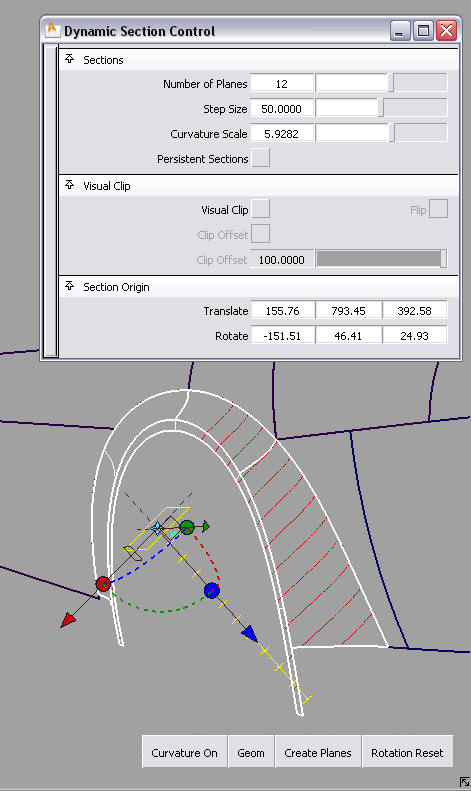
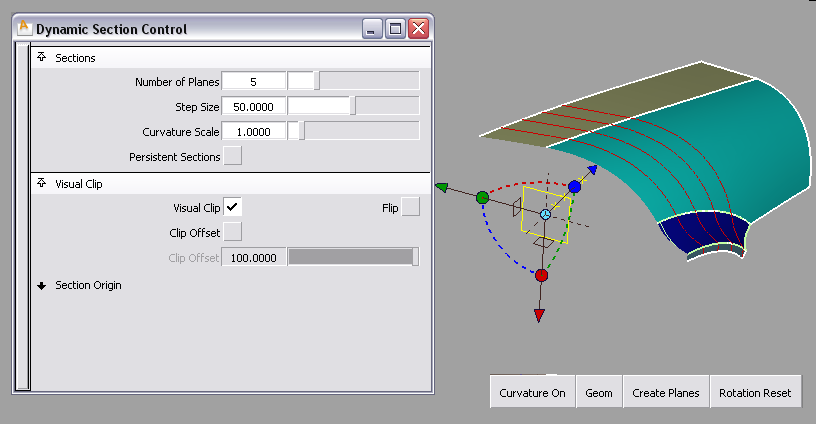
A sectioning plane appears, at the geometric center of the object(s). A red cross section appears on the selected objects
where the plane intersects them.
Note
At any time you can click additional surfaces or meshes to add to the selection. Clicking an already selected surface or mesh
removes it from the selection. (You can use a pick box instead of clicking.)
- Set the (number of sections) and (spacing between sections) in the option box.
The cross sections appear as red lines and update on the objects.
- Use the manipulator to orient the sectioning plane, or enter specific values in the and fields in the control window.
-
Changing these values update the plane manipulator, and vice-versa.
The cross sections update as the plane is moved/rotated.
Note
Using the fields lets you cut a section at a specific location along one of the main world axes (for example X = 100).
- Do any of the following:
- Use the manipulator to move the sectioning plane through the surfaces.
- Select an existing construction plane to use as the base sectioning plane.
- Click the button to create free curves from the cross section(s).
- Click the button to create construction planes corresponding to the sectioning planes.
- Click the button to show a curvature comb plot on the section(s). To change the scale of the comb plot, adjust the setting.
- Click the button to reset all the rotations on the sectioning plane to 0, and re-align the sections with the X, Y, and Z axes.
- Turn on in the control window, to see only the part of the model in front of the sectioning plane. Turn on to see only the part of the model behind the sectioning plane.
- Turn on and to create an additional plane parallel to the sectioning plane, and see only the part of the model between the two planes.
- Turn on in the option box for the sections to remain visible after exiting the tool.
Note
If creating true geometry cross sections with the button, you can use Curve Edit > Sort Sections to sort out your cross sections into different layers, according to the plane they lie in (X, Y, Z or Other). This grouping
is useful for manipulating cross section data.
to sort out your cross sections into different layers, according to the plane they lie in (X, Y, Z or Other). This grouping
is useful for manipulating cross section data.
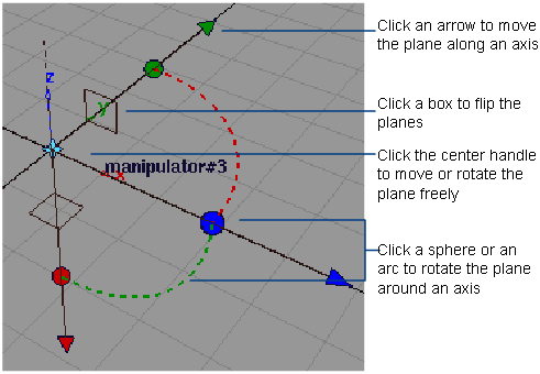
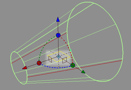
How do I use the manipulators?
Note
The manipulators are visible through shaded geometry.
Sectioning Plane
- Drag a handle to move/rotate.
- Click an arrow to change the center handle to the free move handle. Then drag the center handle to move the plane freely.
- Click a sphere or arc to change the center handle to the free rotate handle. Then drag the center handle to rotate the plane
freely.
- Click a box (square) to set the plane perpendicular to one of the manipulator axes.
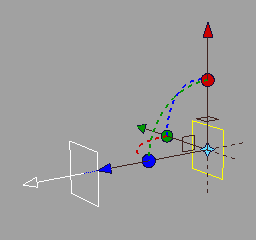
Clip Offset Plane
- Click the plane or the arrow (they turn white) and drag to change the offset distance.
Note
When the sectioning plane is moved or rotated, the offset plane is moved or rotated along with it, so that both planes always
remain parallel and separated by the same distance.
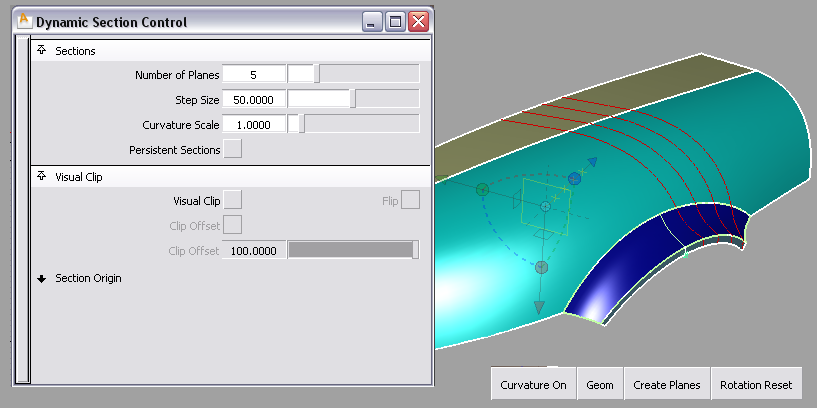
Define two visual clipping planes
You can define a secondary visual clipping plane parallel to, and at a given distance from, the primary clipping plane. Only
the part of the model between the two clipping planes is displayed.
This secondary plane is always driven by the location and direction of the primary plane.
- Select surfaces or meshes
- Choose ❒ to open the option window.
- Adjust position and orientation of the sectioning plane.
- Turn on the option.
The display of surfaces/meshes is clipped to the location and direction of the current plane.
- Turn on the option.
An offset plane appears, and the display of surfaces/meshes is clipped to the location and direction of that second plane
as well, leaving only the part of the model between the two planes visible.
- Use the slider, or click and drag the offset plane manipulator, to adjust the offset distance of the second clipping plane from the
first.
The clipped area updates.
Both the slider value in the option window and the offset plane manipulator on the model update to reflect each other.
Note
To position the offset plane manipulator through keyboard input or snapping, first select it by clicking it without dragging. The manipulator turns white when selected.
Cut a section at a specific location along one of the main axes
- Choose the orientation of the sectioning plane by clicking on one of the three square icons on the manipulator.
- Enter the X, Y, or Z location of the plane in the appropriate field.
Remove persistent sections
If the option was turned on, the sections will remain after exiting the tool.
Use the button in the tab of the Control Panel to remove them.