Creates a reference plane.
You can set the construction planes from reference planes, or use them as input to tools that require a plane.
Reference planes and construction planes
The following tools are used to create a general-purpose plane which can be used as a reference plane or a construction plane:
A reference plane can be used with certain tools, including the Curve Edit > Curve Planarize tool, Curve Edit > Curve Section
 tool, and the
Cross Section Control
section of the Control Panel.
tool, and the
Cross Section Control
section of the Control Panel.
A construction plane allows you to temporarily use a separate coordinate system that can be arbitrarily oriented with respect to the world space coordinate system.
You can easily convert a reference plane to a construction plane and vice versa.
Overview of construction planes
Tools in Alias place objects in an XYZ coordinate system. Normally this is the world space coordinate system, the absolute frame of reference for the universe of your scene.
However, there will be times when you need to align objects in a specific context, where the orientation, position and rotation are different from those of the world space axes and origin.
In these cases, construction planes let you create and work in an alternative coordinate system that can be displaced and rotated from the world space coordinate system.
You can create construction planes that you position and rotate in relation to the world space coordinate system. Construction planes are useful when you are modeling objects that must have an absolute orientation that is not aligned with a major axis.
You can also create construction planes that you position and rotate in relation to a curve or surface. These tools are very powerful, and are useful in a wide variety of modeling contexts.
There can only be one construction plane in a scene (that is, the current construction plane). All other planes are referred to as reference planes. You can convert a reference plane to a construction plane (and vice versa) at any time. You can also use reference planes with certain tools (Curve Planarize tool, Curve Section tool, and the Cross-Sections button in the Control Panel).
For example, consider the following curve. We want to create a surface perpendicular to the curve at its end.
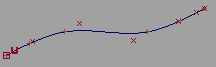
In world space this would be difficult: we would have to draw construction curves for the new surface, then try to rotate the construction curves to be perpendicular to the tangent at the end of the curve.
With construction planes, the task is much easier. With curve snapping  on, we snap the new construction plane to the curve and slide it to the end.
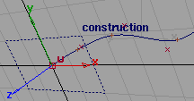
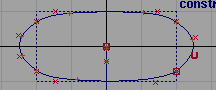
Now we can draw the curves for the new surface much more easily. The grid is perpendicular to the end of the original curve, and the origin of the new coordinate system is the endpoint of the original curve.
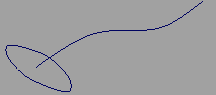
Finally we use the Toggle Construction Plane tool to return to the world space coordinate system. The new construction curve is exactly perpendicular to the endpoint of the original curve. Now we can use Set planar or other surface building tool.
Construction planes and the Perspective window
When a construction plane is active, placement in the perspective window is constrained to the construction plane. This includes:
Mouse buttons in construction planes
You can choose between the following mouse behaviors when using Transform > Move in a perspective window with an active construction plane:
 moves along the X axis of the plane
 button moves along the Y axis of the plane
 moves along the Z axis of the plane
or
button moves freely across the X and Y axis of the plane
moves along the X axis of the plane
moves along the Y axis of the plane
To change between the two control schemes, choose Preferences > General Preferences ❒, go to the Input section, and set the Mouse mapping for perspective move: On construction plane option.


