How to deform surfaces in your animation.
How to transform and manipulate clusters as a single entity.
A cluster is an entity that logically groups an arbitrary list of CVs and DAG nodes so that they can be transformed and manipulated as a single entity. A cluster can be viewed as a type of object that has no geometry of its own, but refers to other geometry.
To create a cluster, pick all the objects and CVs that you want to put in the cluster and choose Animation > Create > Cluster . The CVs do not have to belong to the same piece of geometry. A cluster node is created with a DAG node above it. When this
DAG node is transformed, each of the CVs in the cluster is transformed.
. The CVs do not have to belong to the same piece of geometry. A cluster node is created with a DAG node above it. When this
DAG node is transformed, each of the CVs in the cluster is transformed.
You can move the pivots of the cluster and then transform it using Transform > Rotate or Transform > Scale
 . The CVs of many objects can be transformed relative to a common pivot.
A cluster cannot contain elements that do not have CVs below them. For example, if a camera or light is picked when New cluster is invoked, the camera or light will not be included in the cluster. This is because the purpose of a cluster is to create deformations on object geometry, and cameras and lights contain no geometry.
 ).
).
 , or pick some of the CVs of each of the spheres.
.
, or pick some of the CVs of each of the spheres.
. 
 ) to verify that the cluster has been created. It is displayed as a node with a DAG node above it. The DAG node box is highlighted
and the cluster (an icon of a cluster of grapes) is in a box directly under it.
) to verify that the cluster has been created. It is displayed as a node with a DAG node above it. The DAG node box is highlighted
and the cluster (an icon of a cluster of grapes) is in a box directly under it. 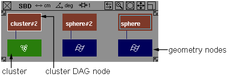
The geometry node (blue node) from which the cluster was assembled has an additional blue box placed around the geometry box indicating that some of the geometry is in a cluster that is picked. If the cluster is unpicked, the blue box around the geometry box disappears.
The new cluster DAG node will be the only item on the pick list after the operation is complete.
You can select geometry in any modeling window to pick all the cluster DAG nodes whose corresponding cluster contains the geometry. Any cluster that contains a selected CV or DAG node will have its DAG node picked and highlighted. You can pick a cluster DAG node in one of four ways:
 then select any CV that belongs to the cluster and the entire cluster is highlighted.
 , all CVs in the cluster will be selected.
You can change the Members state once a cluster has been created in the Cluster Editor window (Animation > Editors > Clusters .
.
Copying a cluster with Edit > Duplicate > Object creates a null node.
Instead, create a new cluster and empty it.
Use the cluster editor to copy the cuts from the original cluster into a new cluster. This will preserve the cluster percentages. Reorder the clusters so that the new cluster immediately follows the original.
Copying cluster members with Edit > Duplicate > Object places the new objects in the same clusters as the original, it will not create new clusters.
Instead, useEdit > Copy and Edit > Paste
 to create a copy of both clusters and members.
How to edit clusters.
Use Animation > Editors > Clusters to allow you to add or remove cluster members, move or copy members between clusters, modify percentage effects of members,
toggle a cluster’s percentage effect type between joint or leaf DAG nodes, or reorder the clusters to set the order in which
the cluster transforms will be applied.
To use the Cluster Editor window
When the Cluster Editor is opened, all clusters specified by the list mode (picked by default or clusters with an active ancestor in the DAG) will be loaded into the Cluster Editor. The clusters are loaded compressed (that is, the members are not visible and are listed according to their global ordering).
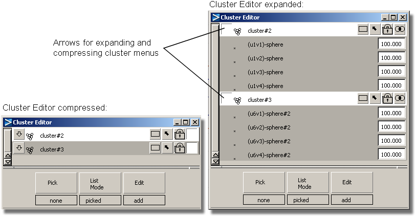
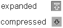
The expand/compress cluster buttons let you expand a cluster to view each of its members, or to compress the cluster to show just the name of the cluster. When a cluster is expanded, members are displayed in the following order: first DAG nodes alphabetically by name, then surface CVs, and curve CVs.
When a cluster is expanded to show its members, a member may be a DAG node. In this case, the DAG node has an expand member arrow to the left of its name. If this arrow is selected, the DAG node is expanded to show everything below it (for example, other grouped DAG nodes, or geometry CVs). If all the siblings of a cluster member are in the cluster (for example, all the CVs of an object are in the cluster), then the member has a compress arrow to the right of its name. If this arrow is selected, the parent DAG node replaces the member and its siblings in the cluster.
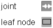
The percentage effect type buttons toggle the percentage effect type of the cluster. The joint percentage effect type tells the cluster to apply its percentage effects to the transformations in the first skeleton joint node that is above the cluster. Leaf node percentage effects tells the cluster to use the transformations in the DAG node directly above it.

The pick-in-modeler button updates the pick state in the modeler for the cluster and its members.
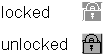
The lock-in-list button ensures that this cluster will remain in the Cluster Editor even if the cluster is unpicked in the modeler.
This is useful in the List Mode > picked mode, where the Cluster Editor will continually update to reflect the currently selected items, and so the cluster would otherwise disappear from the editor if it was unpicked.
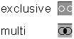
The multi/exclusive button lets you toggle the cluster membership type. An exclusive cluster cannot contain cluster members that are in any other cluster.
Multi-clusters can contain members that are in other multi-clusters. An exclusive cluster can always be made multi; however, a multi-cluster may only be set to exclusive if none of its members belong to any other cluster.
If a cluster is expanded to its CV members, then the CVs are displayed with a percentage to the right of them. This number represents the percentage effect that the cluster has on that CV.
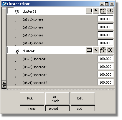
Cluster percentages are a simple extension to clusters that increase their power greatly. Instead of assigning the same transformation to each member of a cluster, the CV cluster members are given a percentage value. When the cluster transformation is applied, each CV in the cluster uses only its percentage of the cluster transformation. The percentage applies to only one DAG node in the hierarchy, depending on the Percentage Effect type (see below).
For instance, if the cluster transformation is a translate of 5.0 in the X direction, a member with a 50% effect translates only 2.5. A member with a 200% effect translates 10.0, and a member with 0% effect remains where it is.
You can change the percentage effect of a CV in the Cluster Editor in two ways: by clicking its current percentage and typing a new value; or by using the micro slider by holding down the mouse button and moving left and right.
To change the percentage of many CVs all at once, select all the CVs in a cluster to have their percentages changed, select the value next to one of the CVs, and enter a new value. All the selected CVs get this new percentage value.
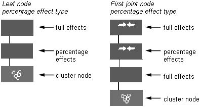
Cluster percentage effect types
By changing the cluster percentage effect type you control which DAG node in the hierarchy above the cluster has the percentages applied to its transformations.
If the leaf type is chosen, the transformations of the DAG node that is directly above the cluster are weighted by the cluster percentages of the cluster. All other DAG nodes in the hierarchy have their full transformations applied.
When the joint type is chosen, the percentage effects are applied only to the first joint DAG node above the cluster. All other DAG nodes in the hierarchy both above and below the first joint node have their full transformation applied to the cluster members.
Joint type percentage effects have an additional feature: the percentage effects are applied only to the difference between the current transformations in the joint and the transformation that was in the joint node when the joint type cluster was created.
If a cluster has its percentage effects type set to joint and there is no joint node above the cluster, it behaves as if its percentage effects type were set to leaf.
For example, suppose that you have a simple chain skeleton with a leaf type cluster under its bottom joint and that the bottom joint’s transformation is a simple rotation of 60 degrees around the Y axis. If you toggle the cluster percentage effect type to joint, the cluster "memorizes" the Y axis rotation.
Now, suppose that you rotate the joint further around the Y axis to 80 degrees. A member with a percentage effect of 50% inherits the original transformation of 60 degrees plus half of the difference between 60 and 80 degrees, resulting in a net transformation of 70 degrees. A member with a percentage effect of 25% rotates by 65% degrees; and a member with a percentage effect of -25% rotates by 55 degrees.
For leaf type percentage effects the original transformation is always assumed to be the identity; that is, the X,Y, Z translates are 0, the X,Y, Z rotates are 0, and the X,Y, Z scales are 1. Continuing the example, if after rotating to 80 degrees you toggled the cluster percentage effect type back to leaf node, the members affected by the cluster would shift. A member with a percentage effect of 50% would now take half of 80 degrees, giving a net transformation of 40 degrees; a member with 25% would rotate by 20 degrees; and a member with -25% would rotate -20 degrees.
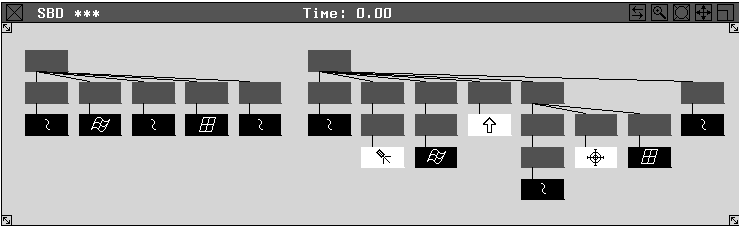
The following illustration shows what percentages look like in the SBD window.
All clusters in the model have a global ordering. It defines the order in which the cluster transformations are applied to a CV that is in more than one cluster (a multi-cluster). If the multi-clusters contain only translation transformations, the order does not matter.
However if the multi-clusters contain rotation or scaling transformations, then the actual position of the CV will depend on the order of the clusters that it belongs to.
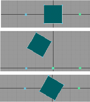
The diagrams illustrate this point. In the first diagram, a plane is created and placed at the origin. The plane is then put into two multi-clusters, one with its pivot to the left of the plane, and the other with its pivot to the right of the plane.
The second and third diagrams show two different effects when the clusters are each rotated 60 degrees. In the second diagram, the cluster with its pivot to the left of the plane is applied first, whereas in the other diagram, the cluster with its pivot to the right of the plane is applied first.
Global ordering is useful to achieve layered cluster effects. For example, suppose that you want to animate a slug by flowing
it along a motion path (see Animation > Tools > Set Motion with the FLOW option), and then animate its eyeballs on top of its eyestalks using a cluster deformation. In that case, the cluster transformation
affecting the eyestalks should occur before the cluster transformation affecting the whole body. If you did Animation > Tools > Set motion before the clusters for the eyestalks were created, then the cluster transformations would be applied in the wrong order,
and the animation would appear incorrect. Reordering these clusters so that the deformation cluster for the eye stalks appears
before the flow clusters will correct the situation.
with the FLOW option), and then animate its eyeballs on top of its eyestalks using a cluster deformation. In that case, the cluster transformation
affecting the eyestalks should occur before the cluster transformation affecting the whole body. If you did Animation > Tools > Set motion before the clusters for the eyestalks were created, then the cluster transformations would be applied in the wrong order,
and the animation would appear incorrect. Reordering these clusters so that the deformation cluster for the eye stalks appears
before the flow clusters will correct the situation.
The order in which clusters are applied to a model can be changed by changing their order in the Cluster Editor.
Click and hold the mouse button on a cluster that you want to move, then drag it and drop it on top of another cluster. This will reorder the clusters so that the selected cluster (which is being dragged) appears directly before the one on which it was dropped, (independent of any other clusters not visible at the time). The current target cluster will be highlighted in white as the dragged cluster moves over it. The Cluster Editor need not show all the clusters in the model; the ones that are present will be in the correct order.
If you want to move several clusters at a time, select them all before starting the drag. All the selected clusters will be placed ahead of the “target” cluster.
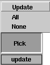
None — all the items in the Cluster Editor will be deselected.
All — all the items in the Cluster Editor will be selected.
Update — update the modeler to reflect the selections in the Cluster Editor.
For example, if there is one cluster and two cluster members picked in the Cluster Editor, then when Pick > Update is selected, the one cluster and two cluster members will be picked in the modeler, and everything else in the Cluster Editor will be unpicked in the modeler. If the selections are conflicting (for example a CV is in two clusters is only selected in the Cluster Editor in one cluster), then the state of the first occurrence in the Cluster Editor takes precedence.
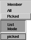
All — all the clusters are loaded into the Cluster Editor.
Picked — if a cluster or one of its DAG node ancestors is picked, then the cluster will appear in the lister.
Member — if any member of the cluster or its descendants are picked, then the cluster will appear in the lister.
Once a cluster has been loaded into the editor, it may be locked in by selecting the lock button. This makes it immune to changes in the pick list.
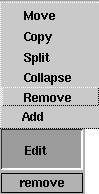
Add — each of the picked items in the modeler are added to each of the selected clusters in the Cluster Editor. Only curve or surface CVs, DAG nodes or other clusters can be added to a cluster.
Remove — each of the selected cluster members are removed from the cluster in which they are selected in the Cluster Editor.
Collapse — for each cluster that is selected, any members of the cluster that are selected have the transformations of that cluster applied to them directly, and then they will be removed from the cluster.
Split — for each cluster selected in the lister, create a new cluster (ordered immediately after the original clusters) and move the selected elements of the original cluster into the new cluster. Either the original or new cluster may be empty (if all or none of the cluster members of the original cluster were selected). The new cluster is of the same type as the original (multi or exclusive). Both clusters are grouped under a common DAG node.
Copy — each selected cluster member in the Cluster Editor is added to each of the selected clusters (without removing them from their original clusters). Percentage animation, if it exists, is also copied.
Move — each of the selected cluster members is moved to the selected cluster. Only one cluster can be selected for this operation. The members are removed from the clusters that they are in and placed in the selected cluster.
Other Cluster Editor functionality
A single click a deselected item selects it, and deselects all other items (cluster or member) in the Cluster Editor.
To select multiple items, hold  down and click the items you want to select or deselect. Or you can hold and click a deselected item, hold down the mouse button and drag-pick to select a group of items. Starting on a selected
item results in unpicking.
down and click the items you want to select or deselect. Or you can hold and click a deselected item, hold down the mouse button and drag-pick to select a group of items. Starting on a selected
item results in unpicking.
Dragging past the ends of the lister scrolls the lister and continue picking or unpicking. Dragging farther past the ends of the window accelerates scrolling.
If only members are selected, then dragging them into another cluster will move the members to the target cluster. The percentage effect on the members is preserved.
How to select handles to make it easier to distinguish between parts of your model and pick them when animating.
 .
.
A pale orange cross and the node name are displayed at the object’s or node’s rotate pivot (the cross looks like the one in the icon). If the selection handle is inactive, the cross and node name become red.
If you are having difficulty seeing the selection handle that you created, you can move it away from the object or node using
Animation > Tools > Move Selection Handle or Transform > Local > Set Pivot
 and opening its options.
Using a cylinder as an example, you can place selection handles on the component nodes and use them to easily activate the components or the cylinder as a whole. To add a selection handle:
. A new handle is displayed at the rotate pivot. 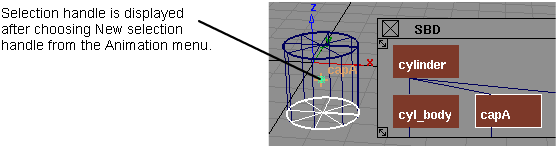
Continue to add new handles as you need them.
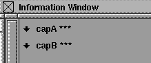
Choose Windows > Information > Information Window for more details on the selection handles you have just inserted into your model.
To delete a selection handle simple select the selection handle and then Delete > Animation > Delete Selection Handles .
.
Change the form of original object in an animation
Set key shape lets you transform one object into another by transforming CVs.
There are two types of interpolations that can be created:
The system prompts:
Pick the curves or surfaces which are to change shape. Press GO when ready.
Enter a keyframe value(s) for the picked item(s) current shape (last frame set is 0):
Setting keyframes for 4 CVs of object (curve#2)
You are then prompted to pick the curve or surface to match and set keyframes for these elements.
How to use key shape interpolations
You are then prompted to select another shape and enter a keyframe time at which the original objects should take on this new shape. Selecting new shapes can continue until all modified copies have been selected and keyframe times are set for them.
The key shape animation is created by animating each of the CVs of the original objects. The interpolation between the CVs (the process that transforms one key shape into another) is, by default, a smooth interpolation. You can adjust this interpolation by modifying the tangents of the animation curves of the CVs in the Action Window.
When you complete the key shape animation, you can delete the animation and start again if you are not satisfied with the
results. However, before deleting the animation, you may want to restore the original shape of the transforming object. If
you typed a keyframe time for the original shape, this is easily done by choosing Animation > Show > View Frame and typing the time of that keyframe.
When satisfied with the animation, you can delete the intermediate objects as their shapes are now recorded as keyframes.
You can use any number of interpolation shapes. Each shape must have identical topology. It is recommended that you copy the original geometry (the geometry shape for the first keyframe), then manipulate the copied geometry into the desired shape for subsequent keyframes. If you are interpolating curve shapes, you can use Curves > New curve and set Knot Spacing to Uniform in the option window to ensure that you create curves with identical topology.
The objects that are used to transform the original object must have the same topology as the original object. Surfaces with same topologies have the same number of CVs in the U and V parametric directions. Curves must have the same number of CVs.
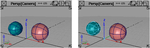
In this example, a sphere is used to create an interpolation animation where the sphere takes on a diamond shape through 10 keyframes, then reverts to its original shape through another 10 keyframes, and back to the diamond in another 10 keyframes.
and place a sphere in the Left window at -5,0,0.
and type 4 to scale the sphere to a value of 4 units.
 ❒ and make sure the CVs is toggled ON (indicated by a check mark). Press GO.
and using the bounding box technique, select only the first row of CVs along the top of the second sphere.
❒ and make sure the CVs is toggled ON (indicated by a check mark). Press GO.
and using the bounding box technique, select only the first row of CVs along the top of the second sphere.
 and use the
  to move these CVs upwards along the Z-axis to elongate the top of the sphere into a pointed shape.
and use the to move these CVs down the Z-axis to elongate the bottom of the sphere into a pointed shape.
and use the
to move these CVs upwards along the Z-axis to elongate the top of the sphere into a pointed shape.
and use the to move these CVs down the Z-axis to elongate the bottom of the sphere into a pointed shape.
and use the  to scale these CVs up to create a bulge in the middle section of the shape, so it resembles the diamond shape shown in the
diagram.
to scale these CVs up to create a bulge in the middle section of the shape, so it resembles the diamond shape shown in the
diagram. 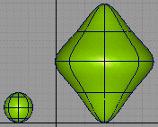
The original sphere defines the start shape and the modified sphere defines the final interpolated shape. Although only two shapes are being used in this example, several interpolated shapes could be used.
Pick the curves or surfaces which are to change shape. Press GO when ready.
If you were including other geometry animation, you would continue to select geometry in response to the prompt.
A small GO icon appears in the lower right corner of the active window, and the system continues to prompt:
Pick the curves or surfaces which are to change shape. Press GO when ready.
Enter a key frame value(s) for the picked item(s) current shape (last frame set is 0):
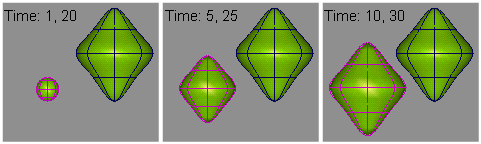
This indicates that the shape of the initial sphere is to be used for keyframes 1 and 20. The system prompts:
Pick the curve or surface to match.
If the surface you select to match does not match the topology of the surface you select to change shape, an error message is displayed and the system prompts:
Pick the curve or surface to match.
If the topology of the selected surfaces match, the system prompts:
Enter a key frame value(s) for this shape (last frame set is 20):
This indicates that the shape of the manipulated sphere is to be used for keyframes 10 and 30.
 to view the interpolation animation.
During playback, the initial sphere shape interpolates into the shape of the manipulated sphere through frames 1 to 10. It then interpolates back to the original shape through frames 10 to 20, then back to the manipulated shape through frames 20 to 30.
How to create ShapeShifter interpolations
With ShapeShifter, an unlimited number of expressions and forms can be combined to transform objects into a variety of shapes, as well as mixing facial expressions together.
ShapeShifter transforms (or “morphs”) one shape into another by transforming CVs using clusters and expressions. This lets you select how much of the interpolation should be applied at any particular time, as well as mix several different target shapes together. Because clusters are used, the underlying geometry can be polygonal or NURBS. Source and target objects can also be hierarchical, as long as the hierarchies match.
ShapeShifter greatly simplifies complex facial animation. For example, given a base (or neutral) face, and other faces that represent a smile and frown, you can create a face which is 75% smiling and 50% frowning and control the timing of the interpolation between the various targets.
The interpolation is done by determining the translation which will make a CV in the source object move to the corresponding CV in the destination object. Therefore the two objects must share the same topology (that is, they must have the same number of CVs in both u and v).
The interaction is simple — for each target, a “control” object is created. The X translation of this object determines the amount of transition from the base to the target object and, of course, can be animated. For example, to have the neutral face ease into a smiling face over two seconds, you simply move the control object to the left of the slider, set a keyframe at 0, then move the control object to the far right and set another keyframe at 60. Set the animation interpolation in the Action Window on the control object’s X_translation channel (or use an expression) and you’re ready to go.
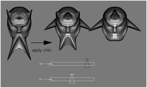
The following example shows how ShapeShifter is used to combine features from two separate head expressions.
The middle head combines the features from the other two heads. The head on the left has been manipulated to exaggerate the chin and horns of a little devil. The head on the right has a pointier head, as well as some devilishly handsome ears.
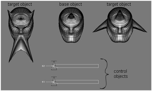
Moving the control object of the top slider causes the middle head to acquire some of the features of the head on the right. Notice how the middle head is also pointier, and has begun to sprout its own pair of ears. The amount of shape-shifting can be controlled by the position of the slider.
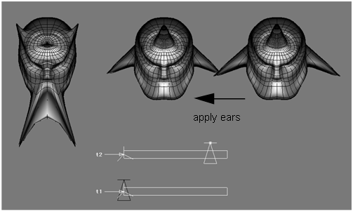
As you start to move the control object of the bottom slider, notice how the middle head begins to acquire some of the characteristics of the left head as well as retaining the effects of the right head.
The source and destination objects must share the same topology (they must have the same number of CVs in both U and V). The interpolation is done by determining the translation which makes the CV in the source object move to the corresponding CV in the destination object.
 ❒ then click ShapeShifter in the Interpolation section of the option box.
A DAG node containing 3 clusters and a DAG node for the control object are created.
Hierarchical ShapeShifter interpolations
ShapeShifter interpolations can also be created between objects consisting of many grouped geometry nodes.
For grouped objects, the Shape Center is created as follows:
The following is an example of the SBD view with two diverse hierarchies, which can still be used for ShapeShifter interpolations. Geometry nodes are matched up going from left to right through each object.
Create clusters with properties for deformation
The Deformation Control window lets you set parameters for a deformation frame, then attach that deformation frame to an object. For a Curve, Axis, Skeleton, or Character Builder deformation, once the deformation frame has been attached to the object, the surface of the object can be modified interactively by manipulating the deformation frame.
Understanding when to use deformation
When an object is required to change shape, the CVs controlling the surface shape can be modified, usually one CV at a time. This gives you flexibility when changing the shape of an object, but it quickly becomes tedious and time consuming when a surface or object is constructed from many CVs.
Deformation control provides a higher level of manipulating CVs by letting you create groups (or clusters) of CVs. It’s like pushing and pulling on the surface, as in clay modeling.
There are four types of deformation frames:
To attach a deformation frame to a model, the Deformation Control window should be displayed on the screen. Once a deformation frame has been attached to the model, the window can be closed.
Choose Animation > Editors > Deformation Control to open the Deformation Control window.
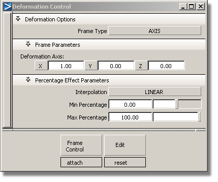
The Deformation Control window updates to reflect the parameters that apply to any of the four types of deformations. The following shows the Deformation Control window with the default settings.
All the parameters that are set in the window are applied to the frame that will be attached to the model. Once the frame is attached, altering the parameters does not affect any changes to a frame already attached to a model.
If you want to change parameters to vary the deformation effect, the window for the SKELETON and CHARACTER BUILDERFrame Types contain a Modify option. Otherwise, the frame currently attached to the object must be detached first, the new parameters set, and then the new frame attached to the model. In some cases you may want to leave the original frame attached to a model, set new parameters and then also attach the new frame to the model.
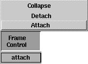
Deformation Control window buttons
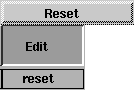
The Frame Control and Edit buttons are located at the bottom of the Deformation Control window. Click and hold on a button to display the associated menu.
A frame’s type defines the kind of deformation clusters created. For some frame types, you need to create a frame object to attach the clusters to.
For example, for a curve frame type, the frame is a curve. For a skeleton or character builder frame type, the frame is a skeleton. The axis frame type requires no explicit frame.
The menu items that are displayed depend on the frame type you specify. The following are applicable to all frame types:
Attach — attaches a frame deformation of the specified frame type.
If no objects are active at the time the Attach function is invoked, the system prompts you to select the objects you want to attach a frame to.
Detach — detaches a frame from a model and cancels any deformations applied to the objects that the frame was attached to.
When a frame is detached from a model, the frame is retained, but all associated deformation clusters are deleted, including any bulging clusters for CHARACTER BUILDER frames.
The detach function for an AXIS deformation is essentially the same as selecting or picking the associated cluster and deleting it with Delete > Delete Active .
.
Collapse — detaches a deformation frame from a model and collapses all the transformations defined by the frame to the attached model.
This way, if the frame is deleted, the deformation effects on the model are retained. The SKELETON, CURVE, or CHARACTER BUILDER frame is retained, but all associated clusters are deleted.
If you choose the SKELETON frame type, the Frame Control menu includes the Modify option. For CHARACTER BUILDER frame types, the Frame Control menu includes the following options:
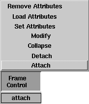
Modify — modifies the way CVs on a frame are currently attached. This is convenient when you change some of the options in the Deformation Control window and want the attach you already performed to reflect the new settings. This operation is essentially identical to doing a Detach followed by an Attach.
Set Attributes — stores the currently displayed character joint and bulging attributes on a picked joint.
If Hierarchy Depth is set to BELOW or PARTIAL BELOW, attributes are also stored on all the joints below the picked joint according to the Hierarchy Depth setting.
Load Attributes — updates the Deformation Control window with the values previously set on a picked joint.
Remove Attributes — removes any previously set attributes from the selected joints.
Lets you specify the frame type you will use for the deformation. Click to the right of the Frame Type heading to display a menu of available frame types.
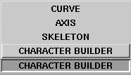
When the type of frame is selected, the Deformation Control window automatically updates to reflect the parameters applicable to that type of frame.
The following describes the different parameters that are displayed for each selected Frame Type.
An AXIS deformation is the simplest of the deformations to use. It creates a single cluster to achieve the deformation effect. The most obvious use of AXIS deformation is for bend, twist, or tapering operations.
The system computes the percentage effects to be used on the CV members of the cluster based on their distance from a plane. The position of this plane is defined by the deformation AXIS parameters.
When Frame Type is set to AXIS, the Deformation Control window updates as shown in the following.
The Deformation Axis parameters are used to specify the direction in which the percentage effects will change.
Click and drag at the bottom of these sliders to select a value, or click to type a new value then press Enter.
The interpolation distance is computed as the world space distance between the object’s CV and a plane that is normal to the deformation axis. The origin of this plane is computed by projecting a bounding box in the axis direction and finding the point at which there will be 0% effect. The easiest way to picture this is to imagine a cylinder as the deforming object. The deformation axis lies in the direction of the long axis of the cylinder. The origin will be at the center of the bottom of the cylinder when the percentage range is 0.00 to 100.00. Each of the DeformationAxis parameters are editable and any deformation axis can be specified.
The Percentage Effect Parameters for Interpolation and the Min/Max Percentage values are the same for the AXIS and CURVE frame types.
Determines how the percentage effect will be distributed among members of CV clusters. Click to the right of the Interpolation heading to display the following menu.
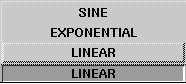
LINEAR — the percentage effect on members of the clusters is distributed based on a linear interpolation between the Min and Max Percentage values.
EXPONENTIAL — the percentage effect on members of the clusters is distributed exponentially between the Min and Max Percentage values.
SINE — the percentage effect on members of the clusters is distributed according to a sine curve interpolation between the Min and Max Percentage values.
The following diagram shows these three interpolation types.
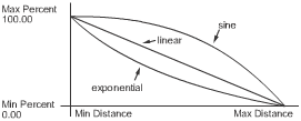
Determines the range of percentage effects that the CVs in the clusters can have. These values can be positive or negative, including a value of 0.00. Although the slider controls have a range of -100.00 through 100.00, values outside of this range can be typed directly into the parameter fields. Reversing the values so the MinPercentage is greater than Max Percentage effectively reverses the direction of the curves shown in the previous illustration.
Using Percentage Effect Parameters for the AXIS Frame Type
 to non-proportionally scale the cylinder to approximately eight units in height.
Pick uninstanced surface(s) to deform, then GO.
Once the prompt clears, the axis deformation frame has been attached to the active objects (the cylinder in this example).
and use the  to rotate along the Y axis. Take note of the effect on the surface. Try other axis rotations and scale functions to experiment.
Clusters can also be selected directly in the SBD window using either Pick > Object or Animation > Pick > Cluster.
to delete the active cluster, returning the model to its original state.
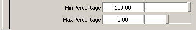
You can also try a Min Percentage value of 100 and a Max Percentage value of 100.
to apply a rotational deformation around the Y axis. The cylinder now twists around the Y axis.
and the cylinder will taper in the respective direction.
In a CURVE Frame Type application, a normal NURBS curve is used as a CURVE frame that influences the deformation. Once the CURVE frame curve is attached to the object, manipulating the CURVE frame deforms the object in the same manner. In a complex deformation, a number of CURVE frames can be attached to an object, each controlling a layer of the deformation. After the initial shape is “roughed in,” it can be easily fine-tuned and applied to the larger model.
When a CURVE frame is attached to an object, a deformation cluster is created for each of the CVs on the frame curve. The frame’s CVs then become handles which can be used to manipulate the frame.
If the Effect Range of a curve deformation is set to MULTIPLE CLUSTER then every handle on the frame affects every CV on the surface, with the handles closets to each CV having more effect than those further away.
If the Effect Range is SINGLE CLUSTER then each CV on the surface is only affected by the handle closest to it.
This example shows the original surface, and then the duplicated curve from the surface generated by the CURVE Frame Type. To create the clusters, each handle on the Curve frame is matched with one or more CVs on the surface. When the Effect Range option is set to SINGLE CLUSTER, the match is determined by matching the surface CVs with the closest frame CV in world space.
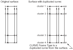
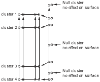
In this example, the CURVE Frame Type is a free-form curve with seven CVs. Three of them are not as close to a CV than the other four. As a result, three null clusters are created. They are displayed in the SBD window, but have no effect on the surface.
When clusters are created, the handle CV of the CURVE frame curve is included in the cluster. In this way, any cluster can be selected easily using Animation > Pick > Cluster and clicking the handle CV that affects the cluster you want to manipulate.
Deformation of the object varies depending on the position of the CURVE frame in relation to the object at the time it is attached. This is because the pivot point of individual clusters are located at the CV location of the handle that affects the cluster.
As you experiment to get a feel for CURVE frame deformations, try aligning the CURVE frame with the center of the object initially, then experiment by attaching the CURVE frame to the object from other locations. Alternately, the pivot point for any cluster can also be repositioned, by picking
the handle of the cluster you want to affect and choosing Transform > Local > Set Pivot.
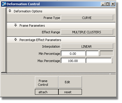
When a CURVE Frame Type is selected, the Deformation Control window updates as shown in the following.
Click to the right of the heading to display the Effect Range menu.
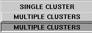
MULTIPLE CLUSTERS — each handle affects all CVs on the object’s surface.
The handle closest to a CV has the most effect, with a diminishing effect from handles that are farther away from the CV.
SINGLE CLUSTER — ensures that the CVs on the object’s surface are only affected by the one handle which is closest to them.
Determines how the percentage effect is distributed among members of CV clusters.
The Interpolation options are the same as for the AXISFrame Type.
The CV closest to the frame CV gets the maximum percentage. The CV furthest from the frame CV gets the minimum percentage. If the minimum is 0, the furthest CV is not clustered.
Using the Percentage Effect Parameters for the CURVE Frame Type
to non-proportionally scale the cylinder so that it is approximately eight units in height.
 to duplicate the vertical isoparametric curve on the cylinder surface that is aligned with the vertical axis at 0,0,0. (Any
other vertical isoparametric curve could be duplicated, then moved to 0,0,0 in world space).
to display the Deformation Control window and make sure the Frame Type is set to CURVE in the menu. All other default settings should be in effect:
to duplicate the vertical isoparametric curve on the cylinder surface that is aligned with the vertical axis at 0,0,0. (Any
other vertical isoparametric curve could be duplicated, then moved to 0,0,0 in world space).
to display the Deformation Control window and make sure the Frame Type is set to CURVE in the menu. All other default settings should be in effect: 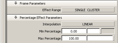
Pick uninstanced surface(s) to deform, then GO.
Select curve(s) to use as frame, then GO
Select the curves you want to use as the frames, (the duplicated isoparametric curve in this case). Once selected, the curves are highlighted.
and drag a pick box over at least part of the cylinder surface and the CURVE frame curve to make both objects active, then click directly on an edge of the cylinder surface to deselect it to make only
the CURVE frame curve active.
The CURVE frame can be moved anywhere once it has been attached to the object, and the pivot points for the clusters remain in the location where the CURVE frame was originally created. Although the pivot points for any individual cluster can be set anywhere at any time, this is an easy way to align them at the center of a cluster. To always maintain the frame and object in their relative positions, simply group them together.
and use the to move the CURVE frame curve off to the right side of the cylinder surface, where it will be easier to manipulate.
and select the CV attached to the second handle from the top of the CURVE frame curve.
Once the cluster is selected, the handle is highlighted as well as all CVs that this handle controls.
and use the to scale the cluster up to deform the surface.
Observe the effect of the deformation in the other modeling windows. All CVs in the clusters are an equal distance from the frame, therefore there is no percentage effect difference between the CVs.
The system prompts:
Pick frame(s) to detach, the GO
Once the cluster is selected, the handle is highlighted as well as all CVs that this handle controls.
and use the to scale the cluster up to deform the surface.
Notice how the percentage effect of the scale ranges from a Min Percentage of 0 to 100 around the periphery of the cylinder because all CVs are no longer an equal distance from the frame curve.
to deform the surface. Experiment with Transform > Rotate and Transform > Non-p Scale.
A shearing effect can be simulated using either of the following deformation techniques.
to manipulate the resulting cluster.
to manipulate the resulting frame to create the shear.
A SKELETON frame deformation lets you attach an existing skeleton to an object, effectively creating a flexible body. The body can then be manipulated by modifying only the skeleton, resulting in much faster feedback. One cluster is created for each joint or bone on the SKELETON frame. These clusters consist of all the CVs that surround the joint or bone.
When a SKELETON Frame Type is specified, the Deformation Control window is updated:
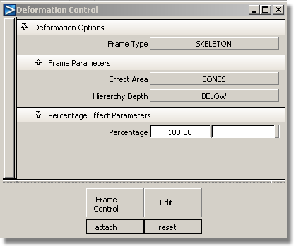
Click to the right of the heading to display the Effect Area menu.
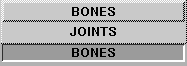
These options let you select whether CVs are grouped by JOINTS or by BONES.
BONES — the CVs nearest to each bone are assembled into a cluster that will be grouped under the upper joint DAG node of that bone. BONES is the default option and is most commonly used.
JOINTS — the CVs in the region surrounding the joint are assembled into a cluster which is grouped under that joint DAG node.
Click to the right of the heading to display the Hierarchy Depth menu.
Because you are specifying how geometry behaves around each joint or bone of the skeleton, it is often useful to limit the number of joints in the hierarchy that will be affected by the current deformation operation.
These options let you specify how many joint levels to consider during an attach.
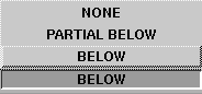
NONE — considers only the current, picked joint as a deformation frame.
BELOW — includes the picked joint and all joints below it in the skeleton hierarchy.
PARTIAL BELOW — includes the picked joint and a user-specified number of joint levels below it.
For instance, picking a joint and specifying a depth of PARTIAL BELOW with two levels will affect a maximum of three joints.
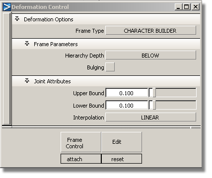
The CHARACTER BUILDER Frame Type extends the SKELETON deformation and lets you specify how the geometry attached to a skeleton bends around a joint and how it bulges between two joints.
For example, bending around a joint provides smooth deformation of arm geometry at an elbow (complete with bending and tucking), and bulging between two joints simulates the biceps as it flexes and influxes due to arm bending.
When the CHARACTER BUILDER Frame Type is specified, the Deformation Control window is updated as shown below.
If the CHARACTER BUILDER Frame Type is selected, when you click the Frame Control button, the menu contains these extra items.
Modify — modifies the way CVs on a frame are currently attached. This is convenient when you change some of the options in the Deformation Control window and want the attach you already performed to reflect the new settings. This operation is essentially identical to doing a Detach followed by an Attach.
The Modify operation in the Character Builder may not work correctly if the Skeleton hierarchy has been used in multiple Attach operations, or if the hierarchy to be modified encompasses a larger hierarchy than was used in Attach.
In Animation > Editors > Deformation Control, do the Modify operation on only one part of the skeleton at a time if all of the following conditions exist:
At least one joint belongs to both hierarchies.
Set Attributes — stores the currently displayed character joint and bulging attributes on a picked joint.
If Hierarchy Depth is set to BELOW or PARTIAL BELOW, attributes are also stored on the joints below the picked joint according to the Hierarchy Depth setting.
Load Attributes — updates the Deformation Control window with the values previously set on a picked joint.
Remove Attributes — removes any previously set attributes from the selected joints.
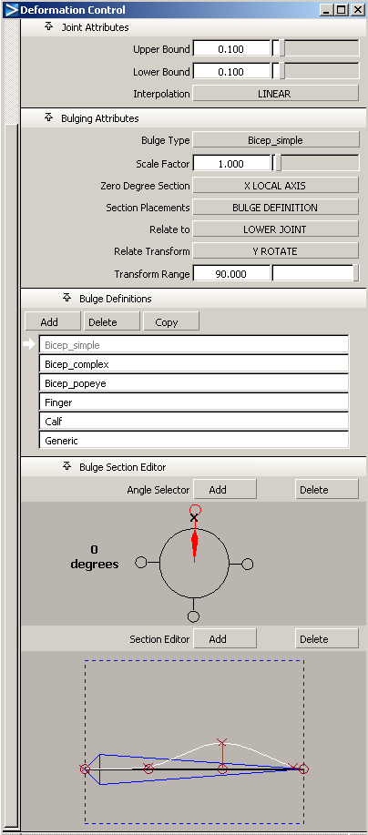
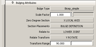
This toggle indicates whether bulging effects should be applied to the joints in the selected hierarchy. Bulging on a joint means that bulging clusters are created for the geometry between that joint and the next lower joint.
When Bulging is ON (indicated by a check mark), the Deformation Control window expands to include joint and bulging attributes, bulge definitions, and the bulge section editor.
These options let you control how smoothly geometry CVs around a joint will bend and tuck at that joint.
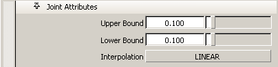
The Upper Bound and Lower Bound values provide a way of specifying how much the transformations at the joint will affect the CVs within those bounds. In other words, these bounds define the region around the skeleton joint where the bending and tucking will occur.
The Upper Bound defines a percentage along the bone from the current joint to its parent joint.
The Lower Bound defines a percentage along each of the bones from the current joint to each child joint.
CVs at the upper bound receive 0% of the transformation (full effects of the upper bone) and CVs at the lower bound receive 100% (full effects of the lower bone). The percentages of the CVs in between are ramped according to the chosen interpolation. It is this ramping of percentages that produces the smooth bending and tucking of geometry as joints are rotated.
Values range from 0.0 to 1.0 and represent percentages of the lengths of the upper and lower bones. For example, if the upper and lower bounds for a joint are 0.25 and 0.333, respectively, all CVs from the bottom quarter of the joint’s upper bone joint to the upper third of the joint’s lower bone are assigned ramped percentages.
Bulge definitions are maintained on a project-by-project basis and are stored in the bulge_types file in the current project’s misc_data directory. All wire files in a project access the same bulges. If this file does not exist when the Deformation Control window is opened, it is created with default bulge types.
Since bulges basically define the way geometry behaves at different locations around a bone, they are comprised of degree sections. Each section represents a profile curve of what the bulge effect will be at a given angle around the bone.
Tells you which direction around the bone represents zero degrees. This is a way for you to specify which slice along a bone will receive the bulge profile that is drawn in the Bulge Section Editor in the Zero Degree Section. Click to the right of the heading to display the Zero Degree Section menu.
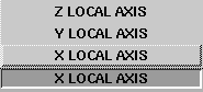
The X, Y, and Z LOCAL AXES choices refer to the local axes of the next lower joint (see Transform > Local > Set Local Axes in Basic Tools for more information).
Determines the location of the clusters that get created during an Attach with Bulging. Click to the right of the heading to display a menu from which you can select the following:
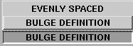
BULGE DEFINITION — creates clusters just as they are defined in the Bulge Section Editor, one cluster for every keypoint in each section.
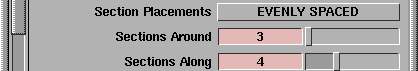
EVENLY SPACED —the bulge’s cluster positions are equally distributed around and along the bone, according to the values specified in the Sections Around and Sections Along sliders.
When you choose EVENLY SPACED from the popup menu, the Bulging Attributes section of the window expands to include the Sections Around and Sections Along parameters.
Click to the right of the heading to display the Relate to menu.
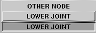
LOWER JOINT — relates the bulge to transformations on the lower joint on the bone. This is the default and would be used for upper arm or thigh muscle bulges.
OTHER NODE — relates the bulge to transformations on any other DAG node, the name of which is entered in the OTHER NODE text box, which only appears when Relate to OTHER NODE is selected. This allows you to create bulging effects when a DAG node in your scene is transformed.
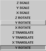
This slider is used to specify a valid range of transformation values from the initial state (at Attach time) that result in bulging. For example, a value of 75 degrees for an upper arm bulge (with Relate set to LOWER JOINT and Relate Transform to Y ROTATE) means that bulging occurs when the y-rotation of the lower joint has values between its current value at the time of attach and that current value plus 75.
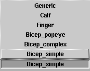
The Bulge Definitions lister is another way of specifying which bulge should be applied on a joint.
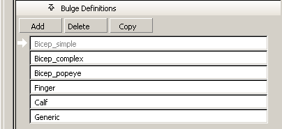
Clicking an entry in the bulge lister selects that bulge and displays it in the Bulge Section Editor. To change the name of a bulge, double click in the field, type a name, then press Enter.
Add — creates a new generic bulge with two sections of three keypoints each.
Delete — deletes the currently selected bulge type.
Copy — copies the currently selected bulge.
Caution! Bulge definitions are stored by code in the bulge_types file and referred to by code in the wire files. If a joint in the current or any other wire file refers to a bulge code that no longer exists, you will not be able to do an Attach.
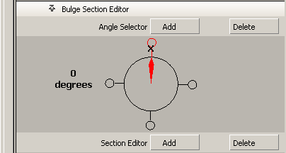
The Angle Selector shows the positions of the sections of a bulge (looking at the Angle Selector is like looking down the bone).
The red pointer indicates which section around the bone is being viewed in the Section Editor. The pointer can be moved around to view different sections of the bone’s bulge definition in five degree increments by clicking and dragging with the mouse. If a section has a curve defined for it, a white “handle” is drawn at that section. This handle can be dragged around and repositioned.
When Add is selected (or is pressed), clicking in the Angle Selector adds new sections. A new section curve will be created as an interpolation of the two curves on either side of it.
When Delete is selected (or  (Windows) or
  (Mac) is pressed), clicking in the Angle Selector removes sections.
When neither one is active, clicking in the Angle Selector repositions the pointer.
The Section Editor shows the bone with a profile curve.
The profile curve’s position around the bone is shown in the Angle Selector. This suggests what the bulge effects look like at different places around the bone. When the Angle Selector points to one of the bulge’s defined sections, the profile curve in the Section Editor turns white and can be modified. Otherwise, the curve is dark and represents an interpolation of the bulge’s effects at that position.
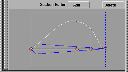
There are two kinds of keypoints in the Section Editor, those represented by x and those by o:
In most cases, the bulge direction will be to be perpendicular to the bone. If the line between o and x is not perpendicular to the bone, the bulge slides along the bone as well as move away from the bone.
In the following example, this is represented in the Section Editor by keypoint A having a perpendicular dropped to the bone. If you grab the o’s along the bone and drag them with the mouse, you change the direction of the bulge. Keypoint B, for instance, will bulge somewhat along the bone axis, toward the lower end of the joint.
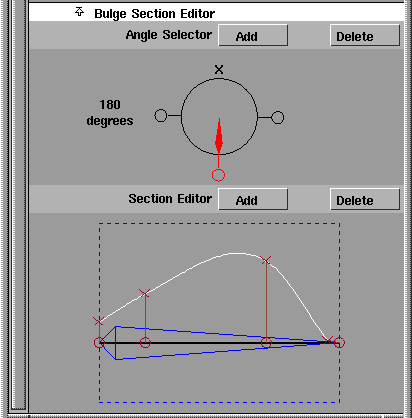
For example, a simple biceps bulge could contain two sections: one above the bone—at zero degrees— with the profile curve resembling a flexed biceps, and the other at 180 degrees with a flat profile curve signifying no bulge below the bone.
The following are restrictions on keypoints in the Section Editor.
The following basic steps show you how to create an arm with smooth bending at the elbow and bulging at the biceps.
Follow these steps to specify bulging on the upper arm. Assume that you have already defined a bulge that has the effects you want and that you’ve called it “biceps.”
and then pick the entire skeleton. This selects the shoulder joint of the skeleton. Modify joint attributes, then press GO
A Go icon is displayed at the bottom right of the current window.
Because you are in Set Attributes mode, any modifications you make in the Bulging Attributes or Joint Attributes sections of the window are stored on the selected joint hierarchy and will be reflected in the representation of the bulge effects displayed in the modeling windows.
Notice that even though Bulging has been turned off in the window, bulging attributes on the shoulder joint have already been set. The state of the options in the window when Attach is selected shows what attributes are used on joints in the hierarchy that don’t have attributes explicitly stored on them already.
You are still getting smooth bending around the elbow, even though you didn’t set Upper and Lower Bound attributes on the elbow joint; those attributes are coming from the current values displayed in the window. (Naturally, the arm should have enough CVs around the elbow to permit smooth bending, and the displayed Bound values should sufficiently bracket those CVs.)
When the Attach operation is completed, apply the desired rotation to the elbow joint and watch the upper arm bulge.
To see the effects of the bulge as you rotate the elbow joint (instead of when you release the mouse button), turn on Expression
Updates: During Transform in the Preferences > Performance Options window.
The CHARACTER BUILDER Attach operation automates two tedious tasks: creating all the bending and bulging clusters and generating the expressions linking bulging clusters to transformations on a DAG node. It is important to remember: