In this lesson, you link the beach house model to 3ds Max Design, adjust the daylight, and add more materials to the scene.
 Start 3ds Max Design.
 Units Setup.
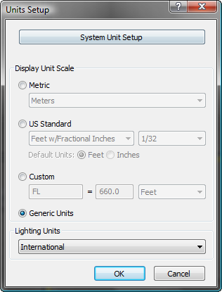
3ds Max Design opens the Units Setup dialog.
3ds Max Design opens the System Unit Setup dialog.
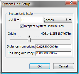
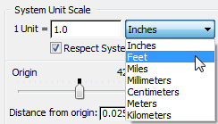
Typically you don’t need to use the System Unit Setup dialog. The exception is when you are importing or opening scenes with a known scale that is different from the typical scale of a 3ds Max Design scene. That is the situation here: Revit always exports FBX files with feet as the unit, so to avoid having 3ds Max Design rescale the FBX model when you import it or link it, you need to set the scale of 3ds Max Design to match that of the FBX file.
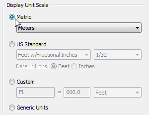
Unlike the System Unit Scale, display units affect only how units are displayed in the 3ds Max Design interface. For this scene, we will work with metric values.
 Application menu, choose
References File
Link Manager.
Application menu, choose
References File
Link Manager.
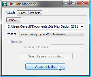
3ds Max Design opens the File Link Manager dialog.
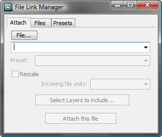
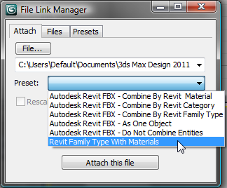
Attach tab, click File.
3ds Max Design sets up beachhouse.fbx as the file to attach.
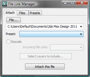
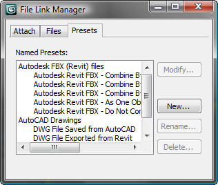
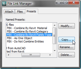
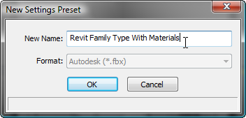
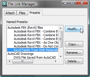
The Presets tab lists a number of presets for linking both FBX and DWG files. On the main Attach tab, you can choose a preset from the Preset drop-down list. You use the Presets tab to edit presets or add a new one.
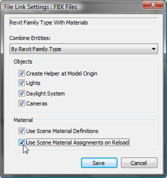
These options ensure that 3ds Max Design materials are preserved when you link a scene or reload a linked scene.
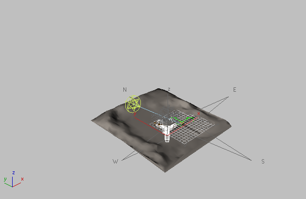
While 3ds Max Design links the FBX file, a progress bar appears in the status-bar area of the 3ds Max Design window, and after some processing the FBX scene appears in the viewports.
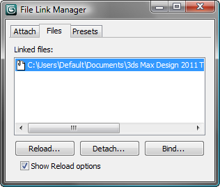
The Files tab shows that beachhouse.fbx is linked to the 3ds Max Design scene. You will use this tab again after making changes to the scene in Revit; for now, you are done with the File Link Manager.
 Close the File Link Manager
dialog.
Close the File Link Manager
dialog.
Adjust the daylight illumination:
3D
View: Exterior.
The viewport switches to the viewpoint of the camera you set up in Revit.
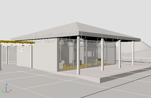
The light objects are visible in the bungalow, but they are turned off because you specified a sun-only export format.
 Motion panel. On the Control
Parameters rollout, notice the settings.
Motion panel. On the Control
Parameters rollout, notice the settings.
The Location is properly set to Boston and the
Time group Month,
Day, Hours, and Mins fields all show the daylight values you set
in Revit.
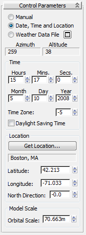
The only change you need to make to the sun is to correct its orientation in the sky, so its rays will be directed onto the terrace and into the living room.
North Direction field, type 300.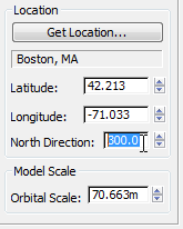
Set the gamma level and add an exposure control:
 (Rendered Frame Window).
 (Environment And Effects
Dialog (Exposure Controls)) to open the Environment And Effects
dialog. Here, you will set the proper exposure for the scene.
(Environment And Effects
Dialog (Exposure Controls)) to open the Environment And Effects
dialog. Here, you will set the proper exposure for the scene.
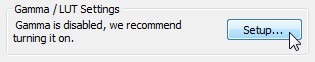
Turn on both options in the Materials and Colors group as well: Affect Color Selectors and Affect Material Editor.
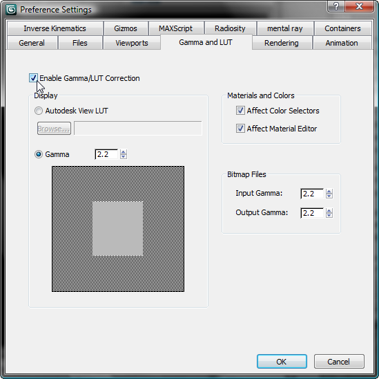
Adding gamma correction improves the appearance of renderings.
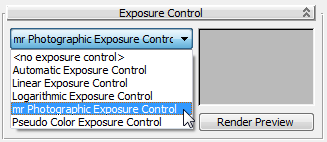
Exposure
group Preset
drop-down list, choose Physically Based Lighting Outdoor Daylight,
Clear Sky.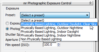
These settings correspond to those you would use with a film camera in comparable lighting conditions.
The house looks good but the terrain appears too regular because it was not optimized in Revit. In the procedures that follow, you will replace the terrain material with a material you create in 3ds Max Design.
Close the Rendered Frame
Window and close the Environment And
Effects dialog as well.
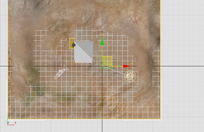
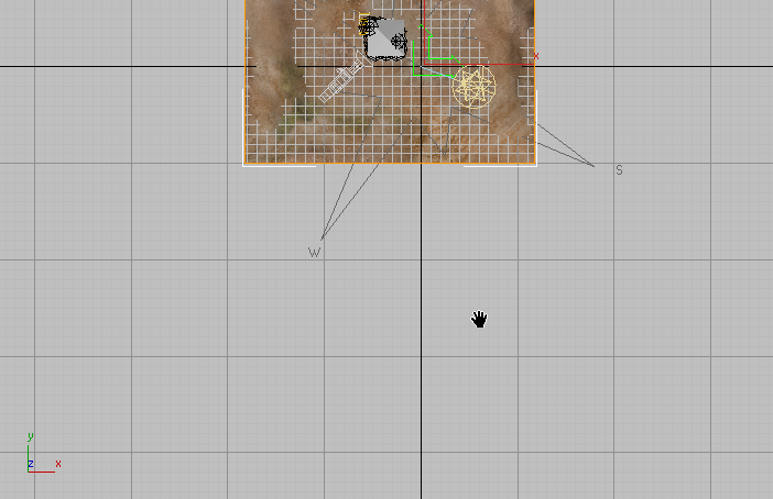
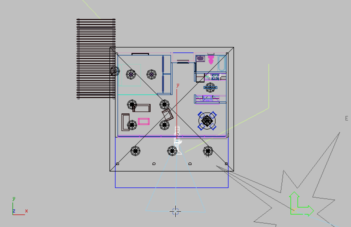
 Switch to a four-viewport
layout, activate the Top viewport, and
Switch to a four-viewport
layout, activate the Top viewport, and  select the object that represents
the terrain.
select the object that represents
the terrain.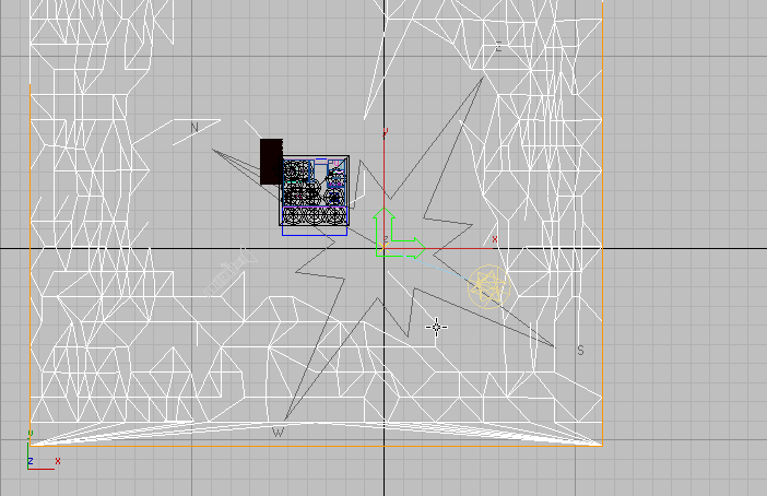
 Modify panel and in the
Name field, change the name to Terrain.
Modify panel and in the
Name field, change the name to Terrain.
As the Modify panel shows, from the 3ds Max Design point of view the Terrain object is simply a linked object from another file.
For the terrain to show a mapped texture in viewports, it needs a UVW Map modifier.
Mapping group, leave
the projection type set to Planar, and turn off Real-World Map Size.
Add a material to the terrain:
 (Material Editor) to open the
Slate Material Editor.
(Material Editor) to open the
Slate Material Editor.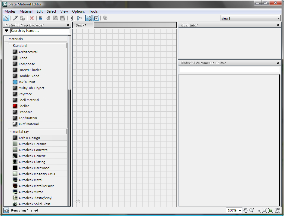
mental
ray group.)
3ds Max Design displays a node for the Generic material in the active View.
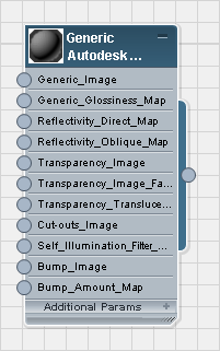
The parameters for the Generic material appear in the Parameter Editor panel at the right of the Slate Material Editor.
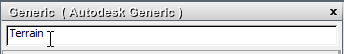
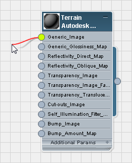
As you update the name in the Name field, the name in the title bar of the material node also updates.
Release the mouse. 3ds Max Design opens a pop-up menu.
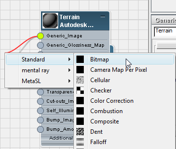
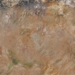
Bitmap used for the seaside terrain
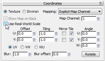
You need to turn off Use Real-World Scale so you can fit the map to the surface object on a one-to-one ratio. For the same reason, leave the Tiling values set to their default values of 1.0 in U and 1.0 in V.
 (Show Map In Viewport).
 (Assign Material To Selection).
Now the texture is visible on the Terrain object in shaded viewports.
Add bump mapping to the terrain:
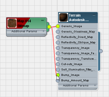
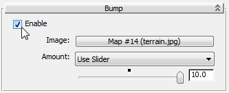
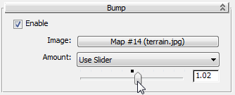
The bump mapping doesn’t appear in viewports, but it will be apparent when you render the scene.
 render the scene.
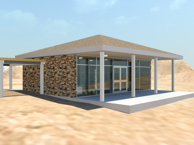
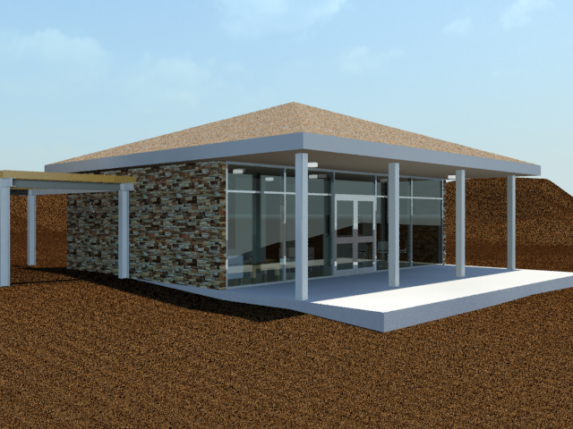
Now the beach house is in the middle of a dry terrain that might be sand dunes.
Next, you will add an object to the scene that represents a body of water.
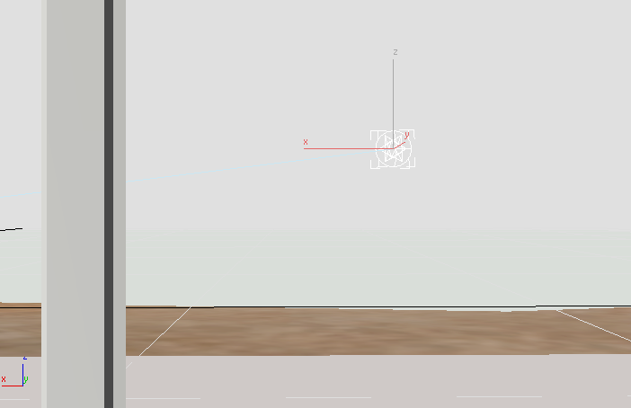
Create a surface that will become the ocean:
 Create panel, click
  (Geometry), and on the Object
Type rollout, click Plane.
(Geometry), and on the Object
Type rollout, click Plane.
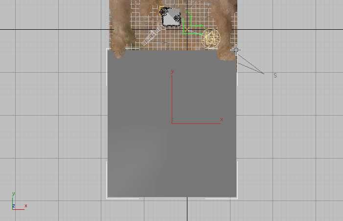
 (Select And Move) to make
it active. Activate the Front viewport. In the Front viewport, move the
plane vertically on the Y axis while you watch the Top viewport.
Stop moving the plane when it intersects the Terrain in a
way that suggests a shoreline.
(Select And Move) to make
it active. Activate the Front viewport. In the Front viewport, move the
plane vertically on the Y axis while you watch the Top viewport.
Stop moving the plane when it intersects the Terrain in a
way that suggests a shoreline.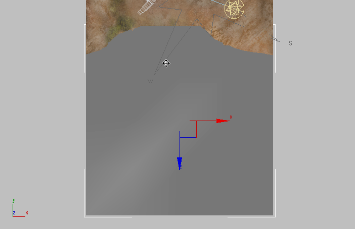
Next, you will resize the plane so it extends out into the horizon.
Modify panel. Change the
name of the plane object to Ocean.
Render Multipliers group Scale field, type 50. 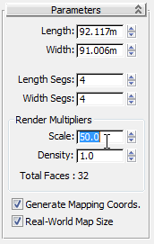
This multiplies the surface of the plane by a factor of 50 each time the scene is rendered. Using the Scale factor can be more convenient than typing object dimensions in the Length and Width fields.
mental ray group.)
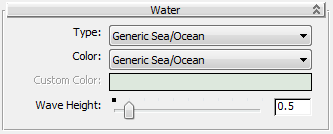
Now you have a water surface for the ocean in your scene. Before you can see the ocean in a rendering, however, you need a new point of view.
Close the Slate Material
Editor.
 (Pan) and
  (Zoom Region) to get a close-up
view of the bungalow.
Create panel, turn on
(Zoom Region) to get a close-up
view of the bungalow.
Create panel, turn on  (Cameras), and on the Object
type rollout, click Target.
(Cameras), and on the Object
type rollout, click Target.
The camera is created at ground level. Now you will raise the camera object to eye level.
Modify panel Clipping Planes group,
and make sure that Clip Manually is turned off.
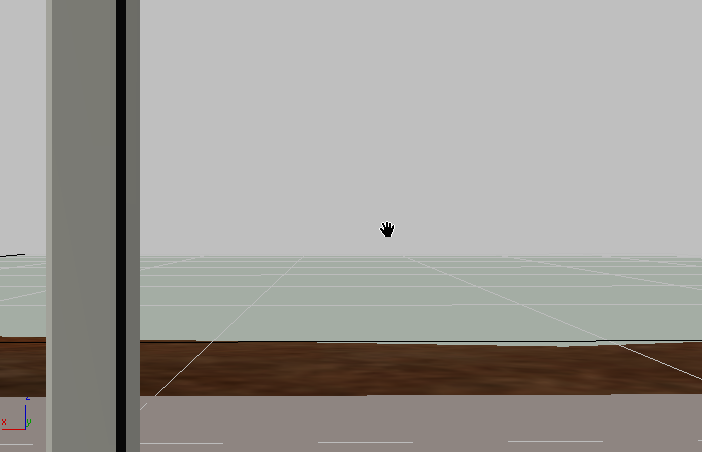
(Pan) and drag downward,
causing the camera and its target (the horizon) to rise from ground
level simultaneously.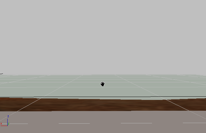
Render the scene.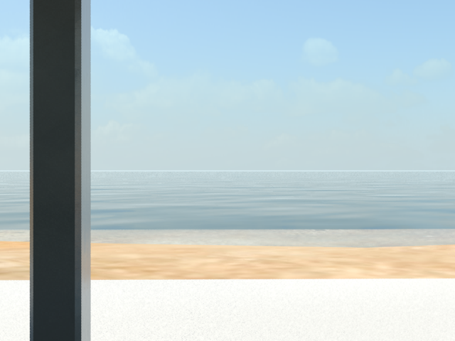
Adjust the time of day and sun position:
To see the beach at sunset, you adjust the time of day and the position of the sun.
 (Zoom Extents), then select the daylight object.
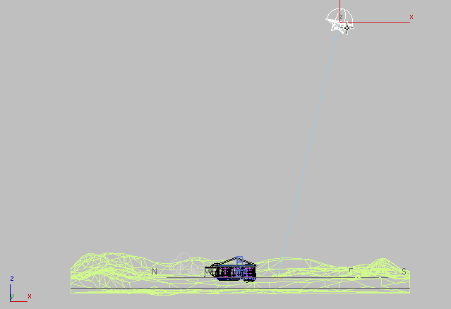
Motion panel Control Parameters rollout,
and in the Time group, change the Hours value to 19,
or 7 PM.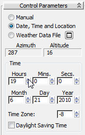
Location group North Direction field,
type 260.0. 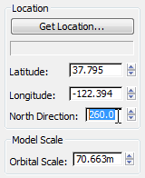
Now the sun is visible in the view from the porch in the Camera001 viewport.
(Rendered Frame Window).
(Environment And Effects
Dialog (Exposure Controls)) to open the Environment And Effects
dialog.
The result is too dark, because the exposure is set for full daylight.
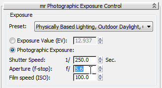
Exposure
group, change the Shutter Speed value to 125.0 (1/125
Sec.).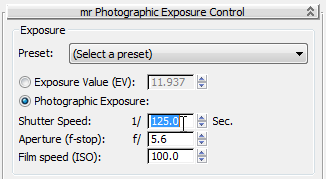
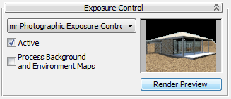
The render preview thumbnail dynamically updates and shows more detail.
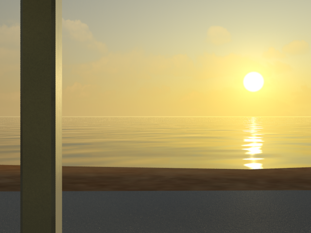
The sun, your repositioned Daylight object, is in full view and the Surface object and plane you created show interesting detail from the materials applied to them.
Restore the time of day and the exterior view:
Time group change the Hours back to 15,
and in the Location group change the North Direction field back
to 300.
mr Photographic Exposure
Control rollout Exposure
group, change the Shutter Speed back to 250 (1/250 Sec.).
Close the Environment And
Effects Dialog.
 dolly back until you can
see all of the carport.
dolly back until you can
see all of the carport.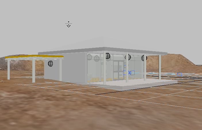
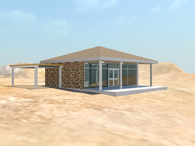
The result is similar to your earlier rendering. In the next lesson, you will change the size of the carport.


