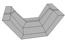
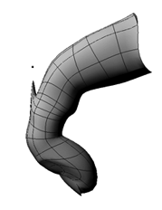
In Softimage, you can select and manipulate points, edges, and polygons directly on a geometric object. This lets you shape the geometry into the form that you want and is an integral part of modeling.
It is important to know that although these techniques may use the transformation tools, they are actually deformations. Each time you manipulate components, a deformation operator is added to the object's stack. Some of these operators, like ConstrainVirtualComponent, don't have any parameters and therefore do not display a property editor; others, like MoveProportional, do have parameters that you can modify. For information about deformations in general, see Deformations.
For information about selecting components to manipulate, see Selecting, especially the topics Overview of Selection and Selecting Components.
The manipulation modes on the Transform panel specify the frame of reference for interaction when manipulating components with various tools. Each transform tool remembers the last reference mode used for components and objects separately.
The translation modes are divided into two groups: the XYZ modes and the drag modes. When you are not using the SRT manipulators, the Global, Local, Object, and Ref modes use the left, middle, and right mouse buttons to transform along the separate X, Y, and Z axes respectively. The View and Plane modes use the left mouse button to "drag" across the corresponding plane.
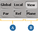
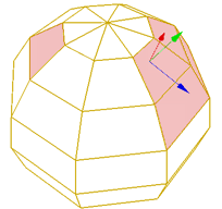
Translation Modes: XYZ modes (A) and Drag modes (B).
Global translations are performed along the scene's global axes.
Local translations are performed along the axes of the components' or clusters' own reference frame. For some more information that is specific to Local mode, see Transforming Components and Clusters in Local Mode.
View transformations are performed with respect to the viewing plane of the 3D view.
Object transformations are performed in the local coordinate system of the object that contains the components.
Ref and Plane transformations can be performed in any default plane (XY, YZ, XZ, or View) as well as any arbitrary reference plane that you specify. For more information, see Reference Planes [Working in 3D Space].
The rotation mode determines the axis of rotation.
Local rotations use one of the local cluster reference frame axes. For some more information that is specific to Local mode, see Transforming Components and Clusters in Local Mode.
View rotations use an axis perpendicular to the viewing plane of the 3D view you are manipulating in.
Ref, or reference, mode lets you rotate elements using the X, Y, or Z axis of another element or an arbitrary reference plane. For more information, see Reference Planes.
Plane mode lets you rotate elements using an axis (by default, Y) of another element or an arbitrary reference plane. For more information, see Reference Planes.
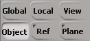
When you are not using the SRT manipulators, the Global, Local, Object, and Ref modes use the left, middle, and right mouse buttons to rotate around the X, Y, and Z axes respectively. The View and Plane modes use the left, middle, and right buttons to rotate about the plane normal (by default, the Y axis) at slow, medium, or fast speed.
Scaling components moves them away from or towards a pivot point. The scaling mode determines the axes along which to scale. If you scale non-uniformly in any mode other than Object, you may get a shearing effect.
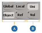
Scaling Modes (A) and Modifiers (B)
Local mode scales along one of the local cluster reference frame axes. Note that as you transform components, their local axes may get recomputed.
Object mode scales along one of the parent object's local axes.
Ref, or reference, mode scales along the X, Y, or Z axis of another element or an arbitrary reference plane. For more information, see Reference Planes.
In addition to the four modes, there are two modifiers that affect how components are scaled:
Uni, or uniform, scales along all active axes at the same time with a single mouse button.
This avoids the annoyance of trying to drag the mouse while pressing two or three buttons. You can activate and deactivate axes as described in Specifying Axes. You can also temporarily turn on Uni by pressing Shift while scaling.
Vol, or volume, scales along one or two local axes, while automatically compensating the other axes so that the volume of a bounding box around the selected elements remains constant.
Local transformations are performed along the components' or clusters' own reference axes. Unlike objects, this reference frame is computed dynamically: it is the average local reference frame of the selected components.
Note that as you transform components, their local axes may get recomputed. Therefore, you might get slightly different results with one larger transformation than with two or more smaller ones.
There are a couple of options that affect how this local reference frame is calculated and used:
Transform Local Components Independently on the Transform menu controls whether adjacent components are treated separately or together. See Transforming Components Independently.
COG controls whether non-adjacent components are treated separately or together when translating. It also controls the pivot point used for rotating and scaling components and clusters. See COG.

Transform Components Independently in Local Mode on the Transform menu controls how adjacent components are scaled, rotated, and translated in Local mode. It has no effect when using other manipulation modes.
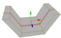
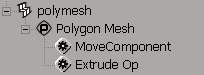
When off, adjacent components are transformed according to their averaged reference frame in Local mode and a single MoveComponent operator is applied.
However, disjoint clusters of connected components are treated separately and one MoveComponent operator is applied per cluster.
When on, adjacent components are not treated as a single cluster in Local mode. Instead, each component is transformed separately according to its individual reference frame, one after the other, and a separate MoveComponent operator is applied for each component.
Because the transformations are applied sequentially when Transform Local Components Independently is on, the local reference frame of one component may change before it gets transformed. This means that you might not get good results in some situations, such as when scaling edges and so on.
COG (center of geometry) on the Transform panel controls how multiple selections of components are manipulated together. Softimage remembers whether COG is on or off for objects and components separately.
When translating, COG controls whether non-adjacent components are translated together or separately.
When it is on, all components are translated along the axes of their average reference frame in Local mode.
COG = on: All components share a single average reference frame as shown by the axes.
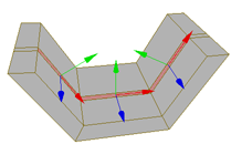
When it is off, non-adjacent components are translated separately along the axes of their own reference frames in Local mode.
Adjacent components are translated together as a single cluster (if Transform  Transform Components Independently in Local Mode is also off).
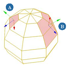
COG = off: Non-adjacent components have their own reference frame (A) and adjacent components share a single average reference frame (B).
When rotating, COG determines the default pivot point used for rotating components and clusters.
When it is on, components rotate about the center of their average reference frame in all modes.
When it is off, components rotate about the center of their own reference frame in Local mode — adjacent components share
an average reference frame if Transform Transform Components Independently in Local Mode is off.
In Global, Object, View, and Plane modes, they rotate about the center of the object that contains them. In Ref mode, they rotate about the origin of the reference plane.
You can also set the pivot manually when using the Rotate tool — see Setting the Tool Pivot.
When scaling, COG determines the default pivot point used for scaling components and clusters.
When it is on, components scale about the center of their average reference frame in all modes.
When it is off, components scale about the center of their own reference frame in Local mode — adjacent components share an
average reference frame if Transform Transform Components Independently in Local Mode is off.
In Global and Object modes, they scale about the center of the object that contains them. In Ref mode, they scale about the origin of the reference plane.
You can also set the pivot manually when using the Scale tool — see Setting the Tool Pivot.
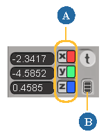
When transforming interactively, you can specify which axes are active using the x, y, and z icons in the Transform panel. For example, you activate rotation in Y only or deactivate translation in Z. Active axes are colored and inactive axes are gray.
Click an axis icon to activate it and deactivate the others.
Shift+click an axis icon to activate it without affecting the others.
You can use relative mode to store component transformations in terms of the component's own coordinate system, rather than the parent object's coordinate system. This affects components manipulated above animated deformations in the construction history, such as when components are manipulated in Secondary Shape Modeling mode above an envelope.
No matter which manipulation mode is used for transforming components, the results are stored relative to the object center by default. If you move the object, the components' offsets are maintained. However if you deform the object, the transformations may not be the same relative to the surrounding components. This may cause undesired results.
In relative mode, the transformations are stored in terms of the component's local coordinate system. If the object is deformed, the components maintain their transformation relative to the surrounding components.
You cannot animate component and cluster transformations directly. Instead, you can use a deformer such as a cluster center (see Cluster Centers) or volume deformer (see Manipulating Points by Volume) and animate it. Another alternative is to use shape animation (see Animating Shapes).
When working in Animation construction mode, you should create a cluster and manipulate that rather than manipulating selected components directly. Otherwise, the operators may not update properly if you later modify the topology.
This is not an issue for operators in the Shape Modeling or Secondary Shape Modeling regions. Once the MoveComponent operator has been baked into a shape, the shape will update properly when the topology is modified.
 Except where otherwise noted, this work is licensed under a Creative Commons Attribution-NonCommercial-ShareAlike 3.0 Unported License